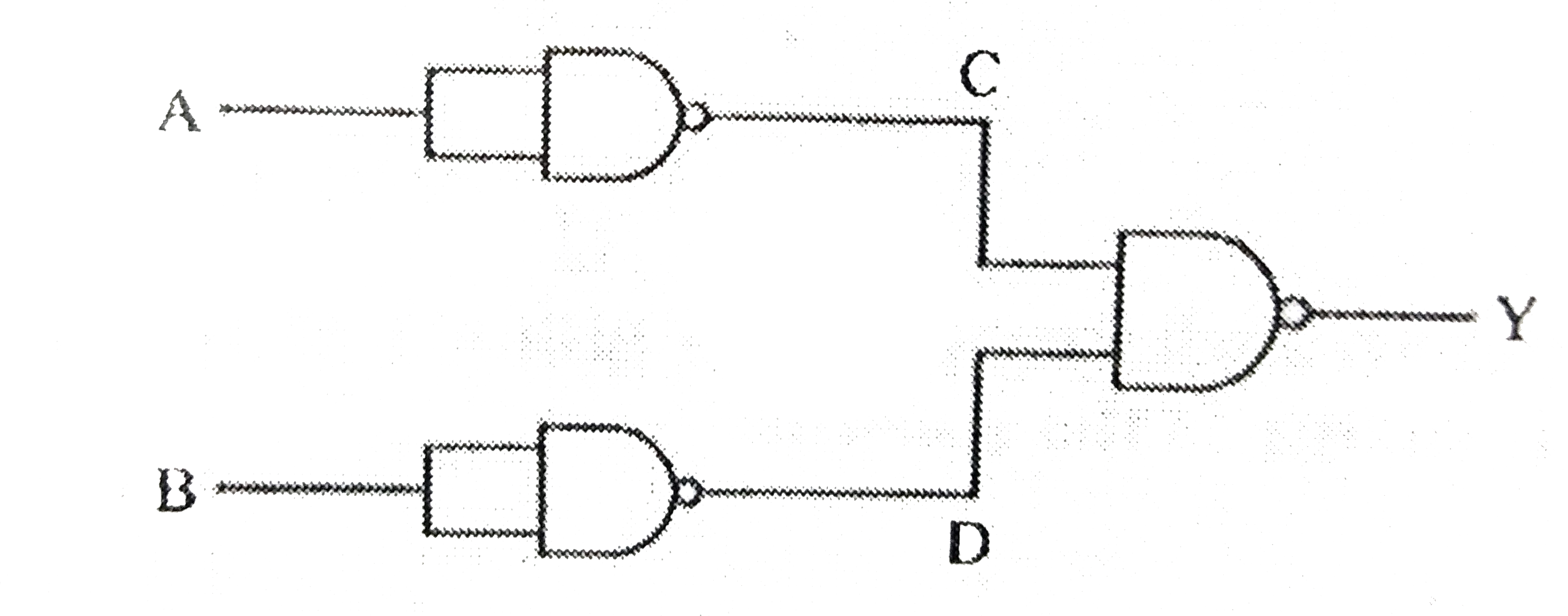
Identify the gate for the two circuits shown below- 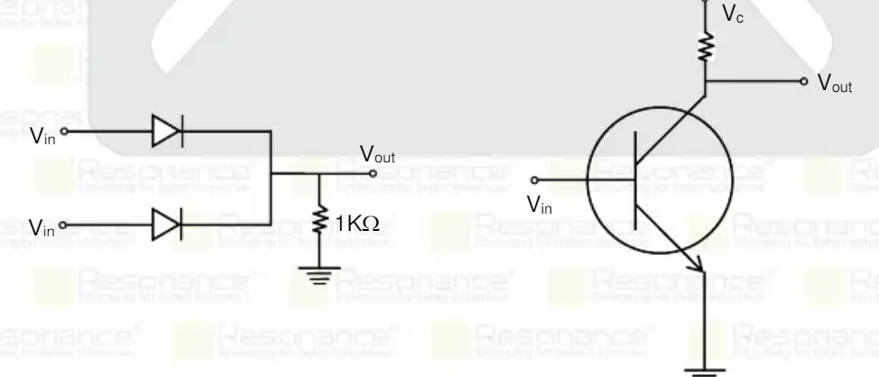
A
AND, NOR
B
OR,NOT
C
AND,NOT
D
NOR,NOT
Video Solution
|
Answer
Step by step video & image solution for Identify the gate for the two circuits shown below- by Physics experts to help you in doubts & scoring excellent marks in Class 12 exams.
Updated on:21/07/2023Topper's Solved these Questions
- JEE MAIN 2021BOOK - JEE MAINS PREVIOUS YEARCHAPTER - JEE MAIN 2021EXERCISE - SECTION-A
80 Videos
- JEE MAIN 2021BOOK - JEE MAINS PREVIOUS YEARCHAPTER - JEE MAIN 2021EXERCISE - SECTION-B
40 Videos
- JEE MAINBOOK - JEE MAINS PREVIOUS YEARCHAPTER - JEE MAINEXERCISE - All Questions
473 Videos
- JEE MAIN 2022BOOK - JEE MAINS PREVIOUS YEARCHAPTER - JEE MAIN 2022EXERCISE - Question
492 Videos
Similar Questions
Knowledge Check
A circuit is shown below.
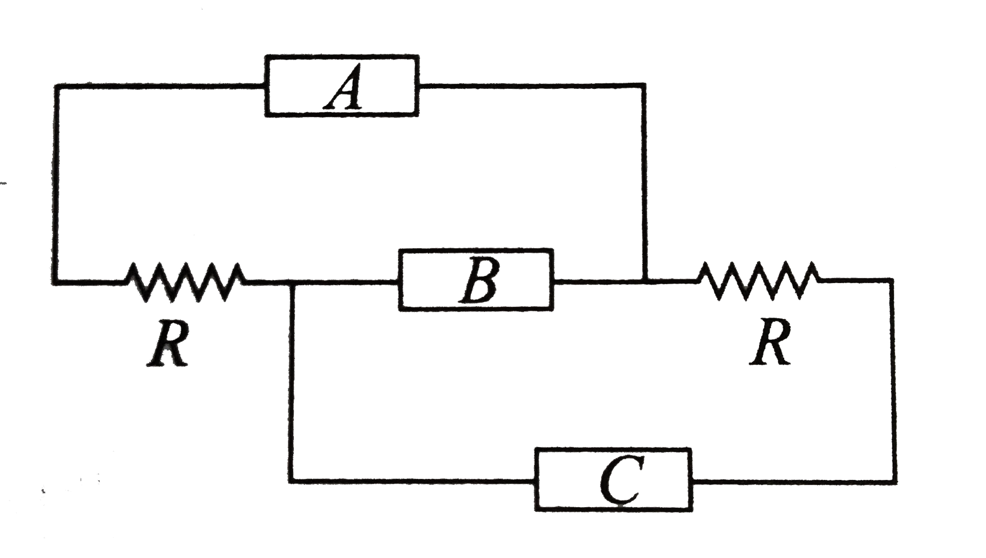 AIf A is an ideal ammeter, B an ideal battery of voltage V, and C an ideal voltmeter, the ratio reading of C/ reading of A is R.BIf A is a capacitor, B an ideal ammeter and C an ideal battery of voltage V, the potential difference across the capacitor is zero.CIf A is an ideal ammeter, B an ideal battery of voltage of V, and C an ideal voltmeter, the ratio reading of C/reading of A isR/2DIf A is a capacitor, B an ideal ammeter, and C an ideal battery of voltage V, the potential difference across the capacitor is 2 V.
The circuit shown below acts as
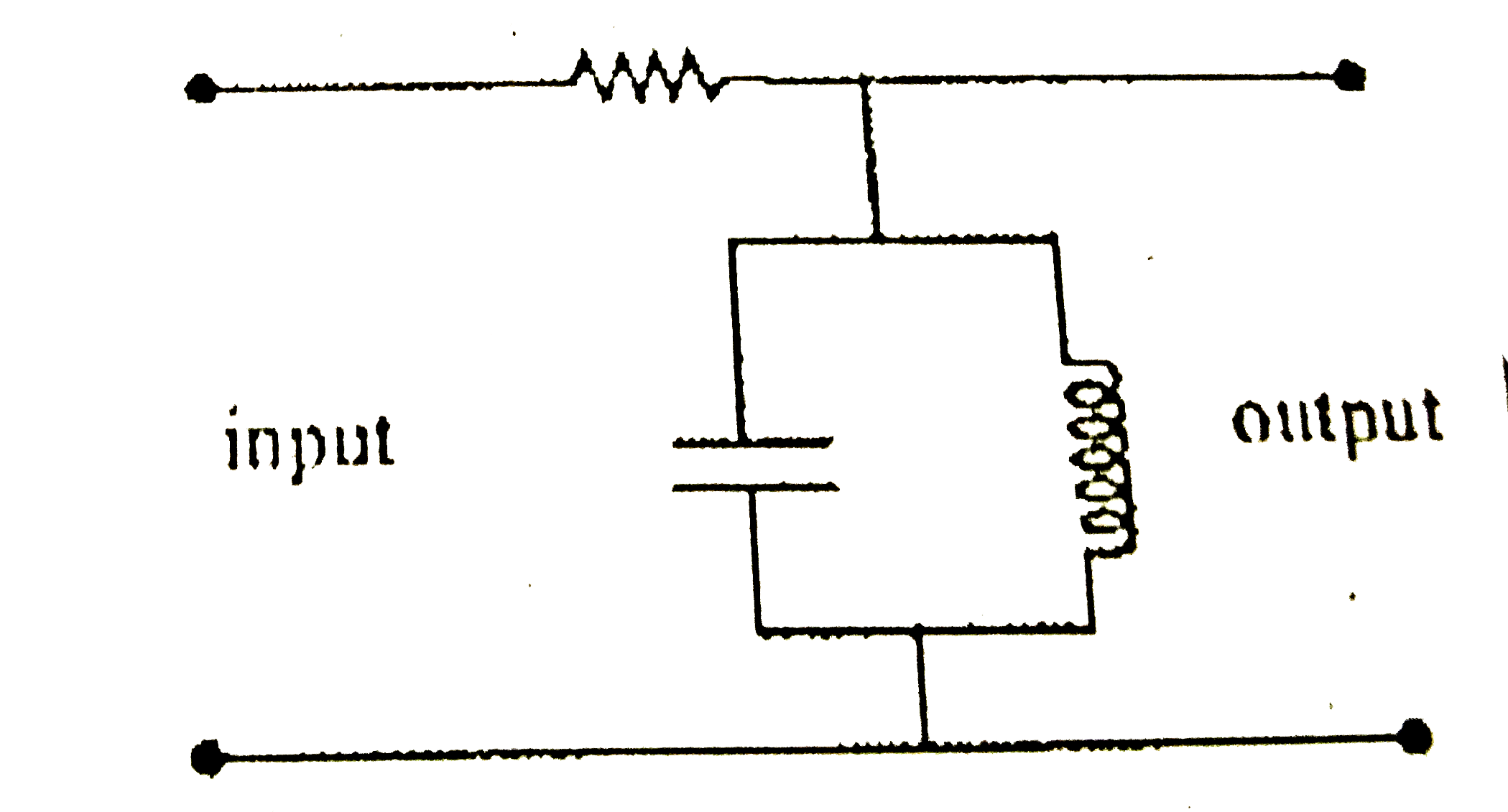 Atuned filterBlow pass filterChigh pass filterDrectifier
The circuit shown below acts as
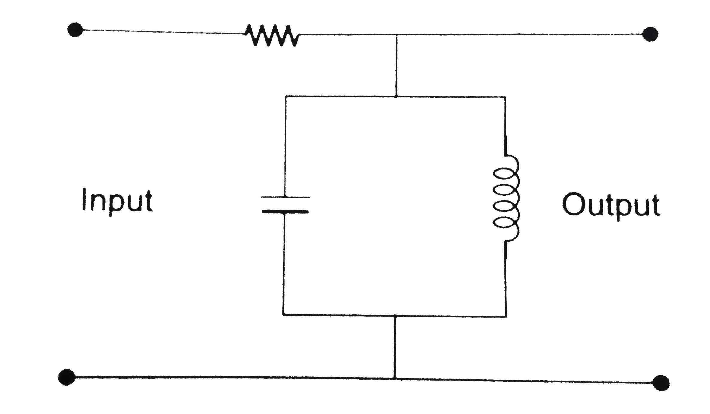 Ahigh pass filterBlow pass filterCtuned filterDrectifier
The power factor for the circuit shown below is
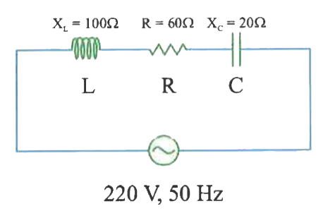
View SolutionThe circuit shown below will act as

View SolutionThe only correct statement for the two circuits (X) and (Y) shown below is :
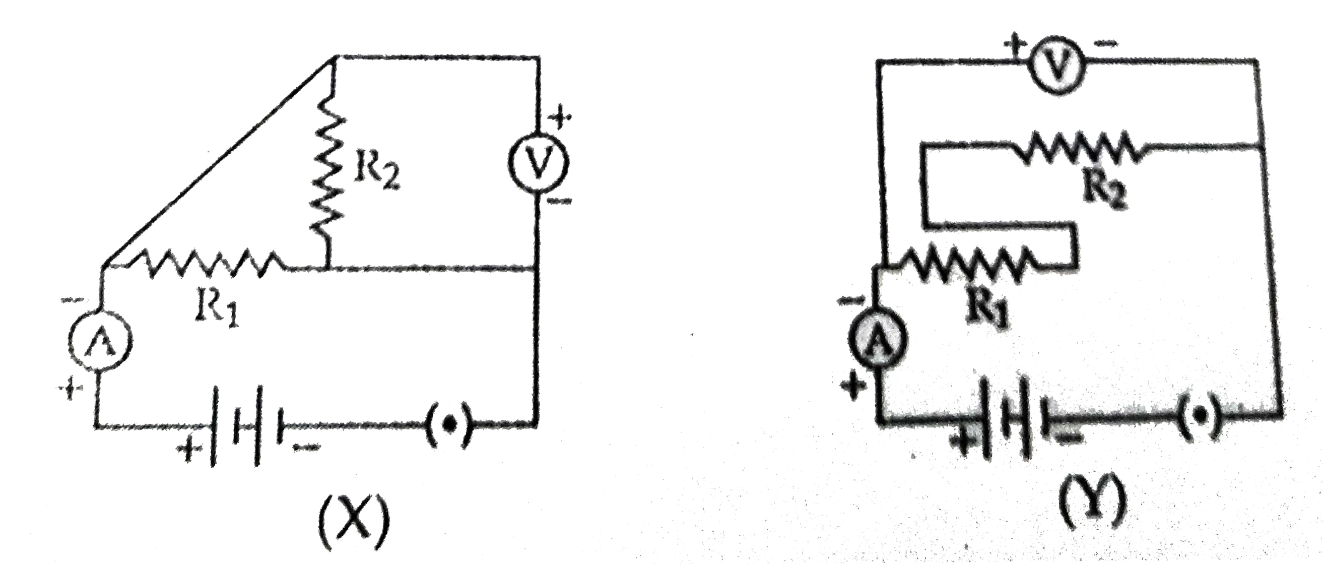
View SolutionOutput of the circuit shown below will be

View SolutionWhat is the current in the circuit shown below?

View Solution

