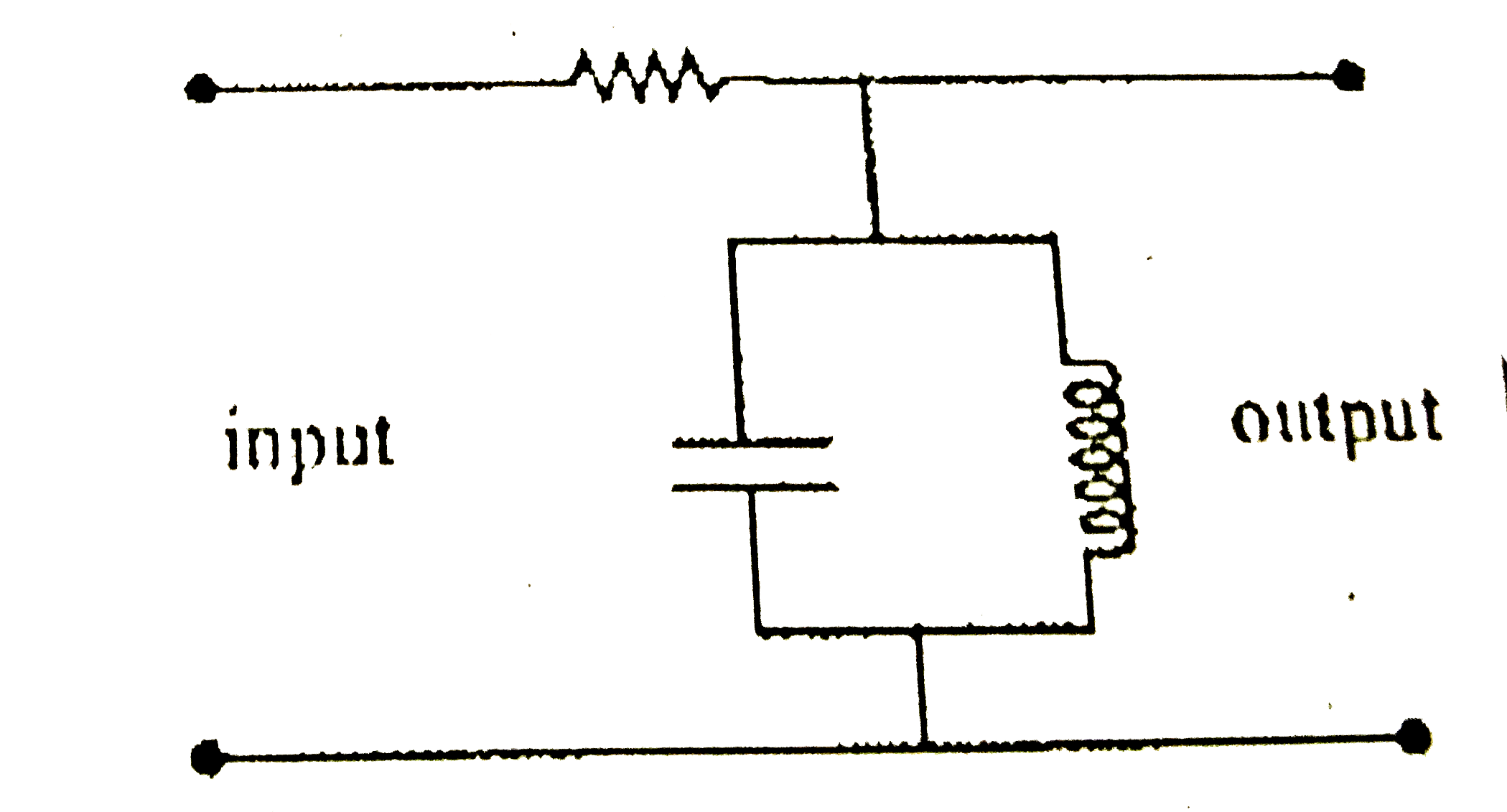
Output of the circuit shown below will be

A
zero all the times
B
like half wave rectifier with positive cycles in output
C
like half wave rectifier with nagative cycles in output
D
like that of a full wave rectifler
Text Solution
The correct Answer is:B
|
Similar Questions
Knowledge Check
The circuit shown below will act as
 AAND gateBOR gateCNAND gateDXOR gate
A circuit is shown below.
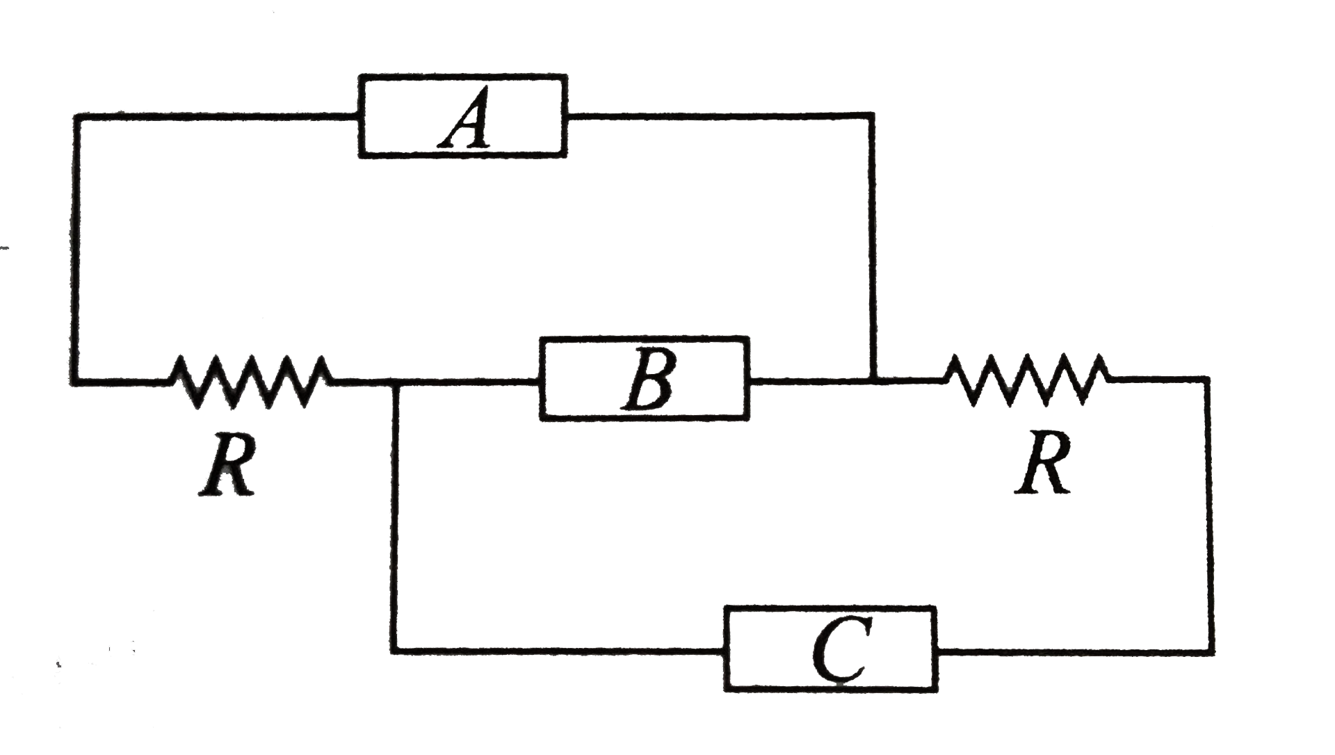
 AIf A is an ideal ammeter, B an ideal battery of voltage V, and C an ideal voltmeter, the ratio reading of C/ reading of A is R.BIf A is a capacitor, B an ideal ammeter and C an ideal battery of voltage V, the potential difference across the capacitor is zero.CIf A is an ideal ammeter, B an ideal battery of voltage of V, and C an ideal voltmeter, the ratio reading of C/reading of A isR/2DIf A is a capacitor, B an ideal ammeter, and C an ideal battery of voltage V, the potential difference across the capacitor is 2 V.
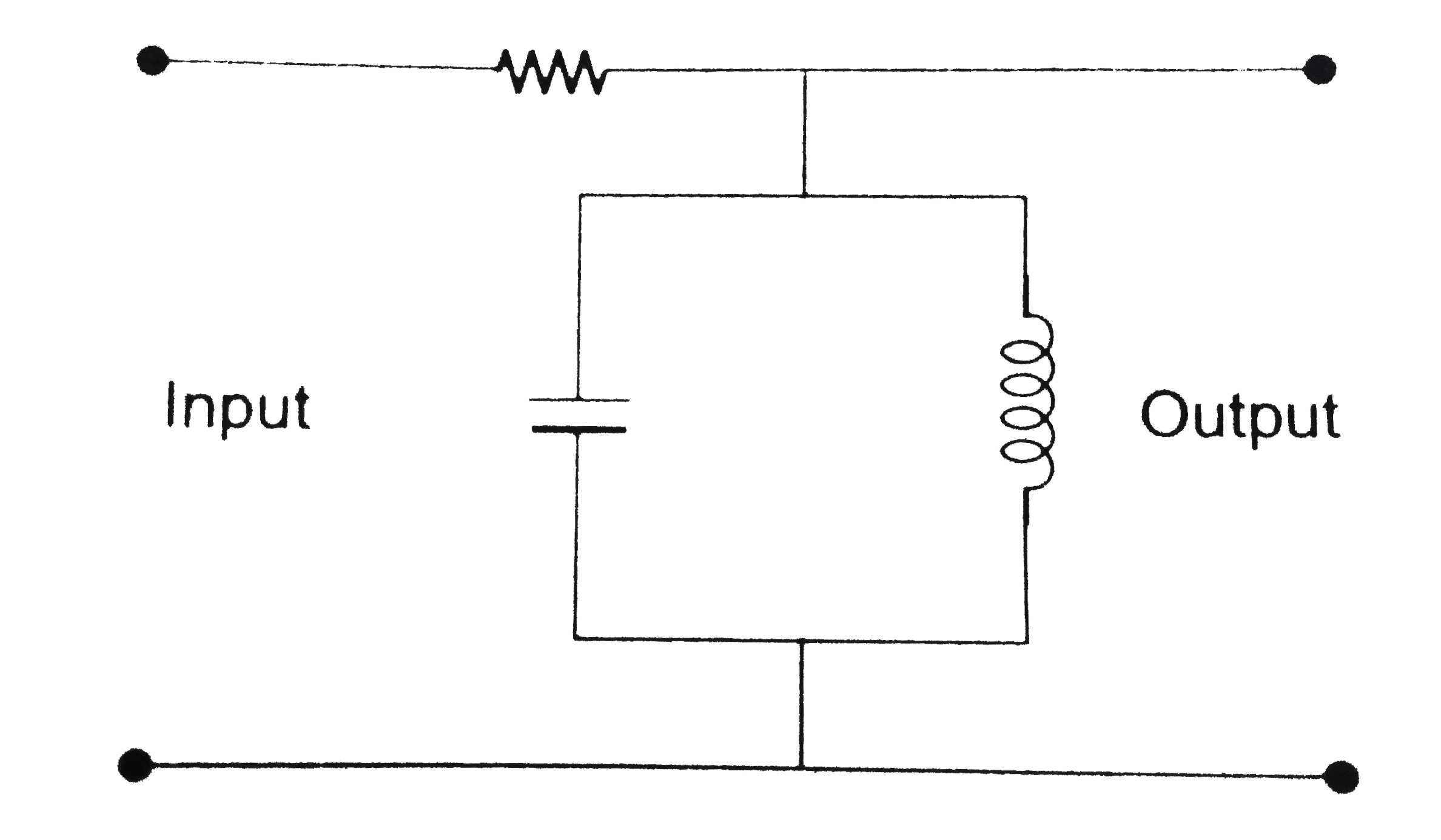
The circuit shown below acts as
 Atuned filterBlow pass filterChigh pass filterDrectifier
The output Y of the logic circuit given below is

View SolutionThe circuit shown below acts as

View SolutionTo get an output y=1 from the circuit shown below, the input must be

View SolutionThe output Y of the gate circuit shown in the figure below is

View SolutionThe output Y of the gate circuit shown in the figure below is

View Solution
