An LCR circuit is equivalent to a damped pendulum. In an LCR circuit the capacitor is charged to Q0and then connected to the L and R as shown below:
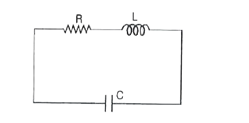
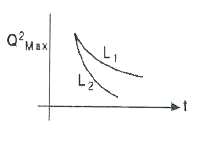
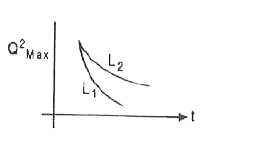
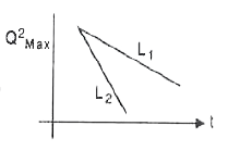
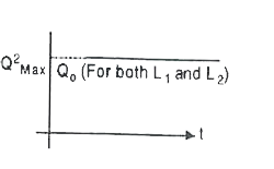
IF a students plots graphs of the square of maximum charge on the capacitor with time (t) for two different values L1andL2(L1>L2) then which of the following represents this graph correctly?
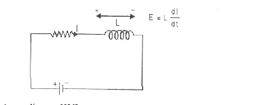
According to KVL,
qC−IR−LdIdt=0
[∵I=−dqdt]
⇒qc+dqdtR+Ld2qdt2=0
⇒d2qdt2+RLdqdt+qLC=0
This is the eqn. of damped harmonic electrical oscillator.
Solution of above eqn. Q=Q0e−Rt2L
⇒Q2=Q22e(−RL)t
Topper's Solved these Questions
- E.M. INDUCTION AND A.C. CURRENTS BOOK - MODERN PUBLICATIONCHAPTER - E.M. INDUCTION AND A.C. CURRENTS EXERCISE - RECENT COMPETITIVE QUESTIONS
31 Videos
- E.M. INDUCTION AND A.C. CURRENTS BOOK - MODERN PUBLICATIONCHAPTER - E.M. INDUCTION AND A.C. CURRENTS EXERCISE - MULTIPLE CHOICE QUESTIONS LEVEL-II
51 Videos
- DESCRIPTION OF MOTION IN TWO AND THREE DIMENSIONBOOK - MODERN PUBLICATIONCHAPTER - DESCRIPTION OF MOTION IN TWO AND THREE DIMENSIONEXERCISE - Revision TEST
36 Videos
- ELECTROMAGNETIC WAVESBOOK - MODERN PUBLICATIONCHAPTER - ELECTROMAGNETIC WAVESEXERCISE - RECENT COMPETITIVE QUESTIONS
4 Videos
Similar Questions
An LCR curcuit is equivalent to a damped pendulum. In an LCR circuit the capacitor is charged to (Q0) and then connected to the L ans R as shown below.
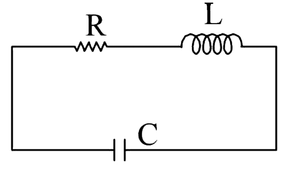
If a student plaots graphs of the square of maximum charge (Q2max) on the capacitor with time (t) for two different values L1andL2(L1>L2) of L then which of the following represents this graph correclty? (plots are schematic and not drawn to scale).
View SolutionAn LCR curcuit is equivalent to a damped pendulum. In an LCR circuit the capacitor is charged to (Q0) and then connected to the L ans R as shown below.

If a student plaots graphs of the square of maximum charge (Q2max) on the capacitor with time (t) for two different values L1andL2(L1>L2) of L then which of the following represents this graph correclty? (plots are schematic and not drawn to scale).
View Solution
Knowledge Check
An LCR curcuit is equivalent to a damped pendulum. In an LCR circuit the capacitor is charged to (Q0) and then connected to the L ans R as shown below.

If a student plaots graphs of the square of maximum charge (Q2max) on the capacitor with time (t) for two different values L1andL2(L1>L2) of L then which of the following represents this graph correclty? (plots are schematic and not drawn to scale).A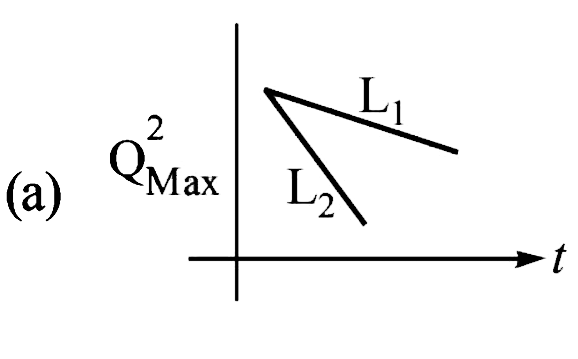 B
B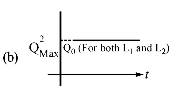 C
C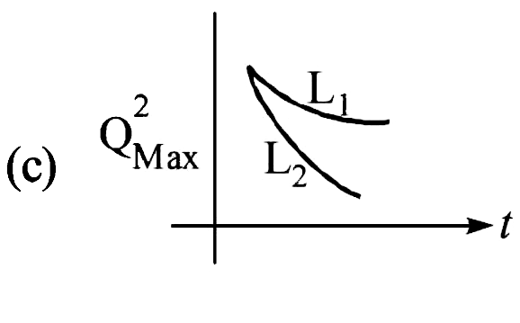 D
D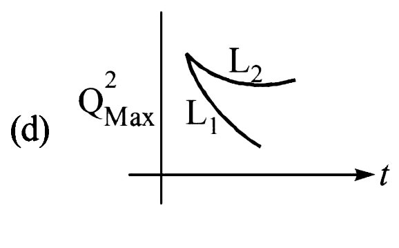
An LCR circuit is equivalent to a damped pendulum In an LCR circuit the capacitor is charged to Q0 and then connected to the L and R as shown below : Thus potential energy stored in the capacitor and that in the inductor also oscillates between maximum value an zero with double the frequency.
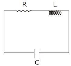
If a student plots graphs of the square of maximum charge (Q2max) on the capacitor with time (t) for two different values L1andL2(L1>L2) of L then which of the following reprersent this graph correctly ? (Plots are shematic and not drawn to scale )A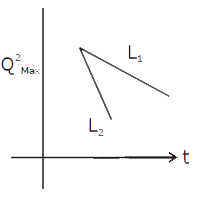 B
B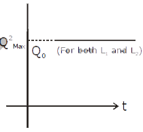 C
C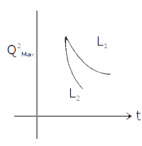 D
D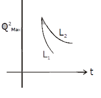
In LCR circuit, capacitor C is changed to 4C, then what should be the value of L to keep resonance frequency same
A2 LBL/2CL/4D4L
A L-C-R circuit is equivalent to a damped pendulum . In an L-C-R circuit the capacitor is charged to Qo and then connected to the L and R as shown below.
If a student plots graph of the square of maximum charge on the capacitor with time (t) for two different values L1 and L2 (L1gtL2of L), then which of the following represents this graph correctly (plots are schematic and not drawn to scale)

View SolutionA capacitor of capacitance Chas initial charge Q0 and connected to an inductor L as shown. Att=0 switch S is closed. The current through the inductor when energy in the capacitor is three times the energy of inductor is

View Solution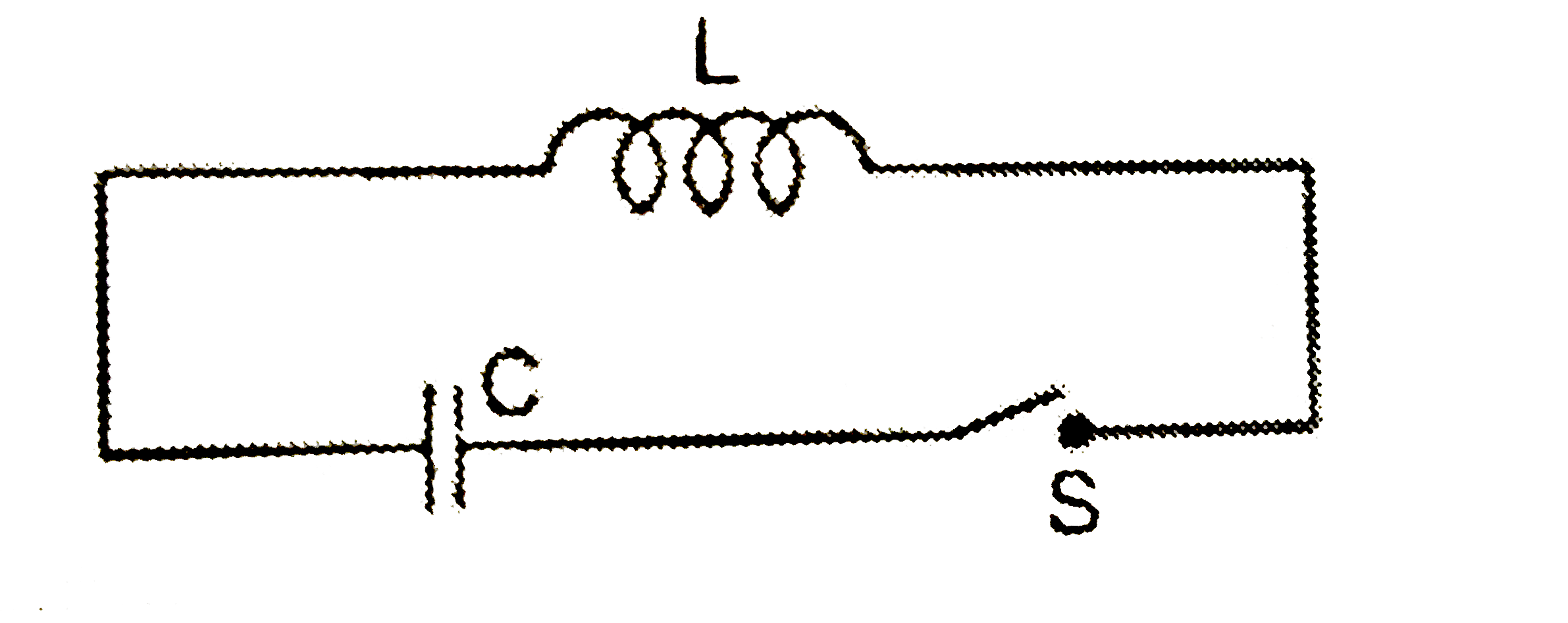
The capacitor of capacity C is given charge Q and then connected to the coil of inductance L by closing the switch S. The maximum current flowing in the circuit at any later time will be
View SolutionA capacitor of capacitance C is given charge Q and then connected in parallel to a coil of inductance L. There is no resitance in the circuit. When the charge on the capacitor becomes zero, the current in the coil will be
View SolutionThe current in an L - R circuit in a time t = 2L / R reduces to-
View Solution
