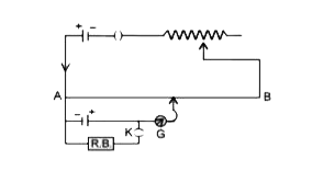
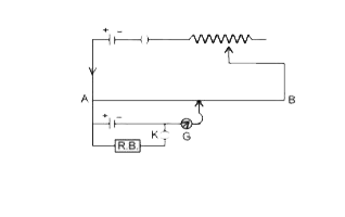
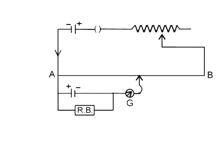
Draw the circuit diagram of a potentiometer to determine the internal resistance of a cell and briefly describe the procedure.
Close key (k) and adjust a suitable constant current in the potentiometer wire with the help of rheostant .
Insert the plug in the gap between the terminal 1 and 2 of two - way key so that the cell of emf E1 is in the circuit . Adjust the position of jockey on potentiometer wire , where if preseed , the galvanomter shows no deflection . Let it be when jockey be at J1 . Note the lenght , AJ1(=l1) of the wire . The emf of the cell (E1) is equal to potential difference between the points A and J1 of the potentiometer wire
E1=Kl1 ........(i)
where , k is the potential gradient across the potentiometer wire .

Now remove the plug from the gap between 1 and 3 and insert in the gap 2 and 3 of two - way key so that cell of emf E2 comes into the circuit. Again find the position of jockey on potentiometer wire , where galavnometer shows no deflection , let it be at J2 . Note the lenght of the wire AJ2(=l2) , then
E2=kl2 ..........(ii)
From Eqs. (i) and (ii) , we get
E1E2=l1l2
Similar Questions
Knowledge Check
The internal resistance of the cell can be determined by,
Aohm meterBgalvanometerCvoltmeterDpotentiometerThe internal resistance of a cell by potentiometer is given by
Ar1=R1(l1−l2l2)Br1=R1(E1−V1V1)Cboth 'a' and 'b'Dneither 'a' nor 'b'Correct diagram for the determination of internal resistance of a primary cell by potentiometer
A B
B C
C DNone of the above
Write the principle of working of a potentiometer. Describe briefly, with the help of a circuit diagram, how a potentiometer is used to determine the internal resistance of a given cell.
View SolutionWrite the principle of working of a potentiometer. Describe briefly, with the help of a circuit diagram, how a potentiometer is used to determine the internal resistance of a cell.
View SolutionDraw a circuit diagram for the determination of the internal resistance of a cell using potentiometer. Derive the formula to be used.
View SolutionThe internal resistance of a cell by potentiometer is given by
View SolutionA 2.0V potentiometer is used to determine the internal resistance ofa I.SY cell. The balance point of the cell in the open circuit is obtained at 75cm. When· a resistor of 10Ω is connected across the cell, the balance point shifts to 60cm. The internal resistance of the cell is:
View Solution
