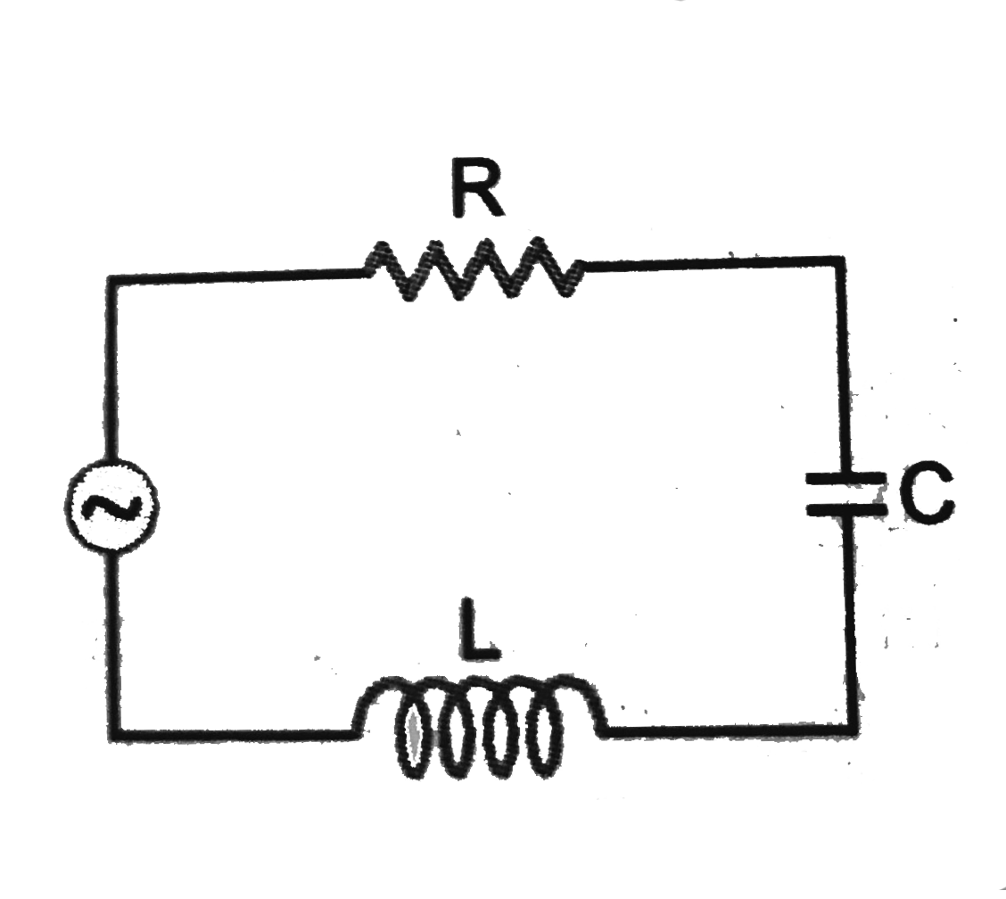
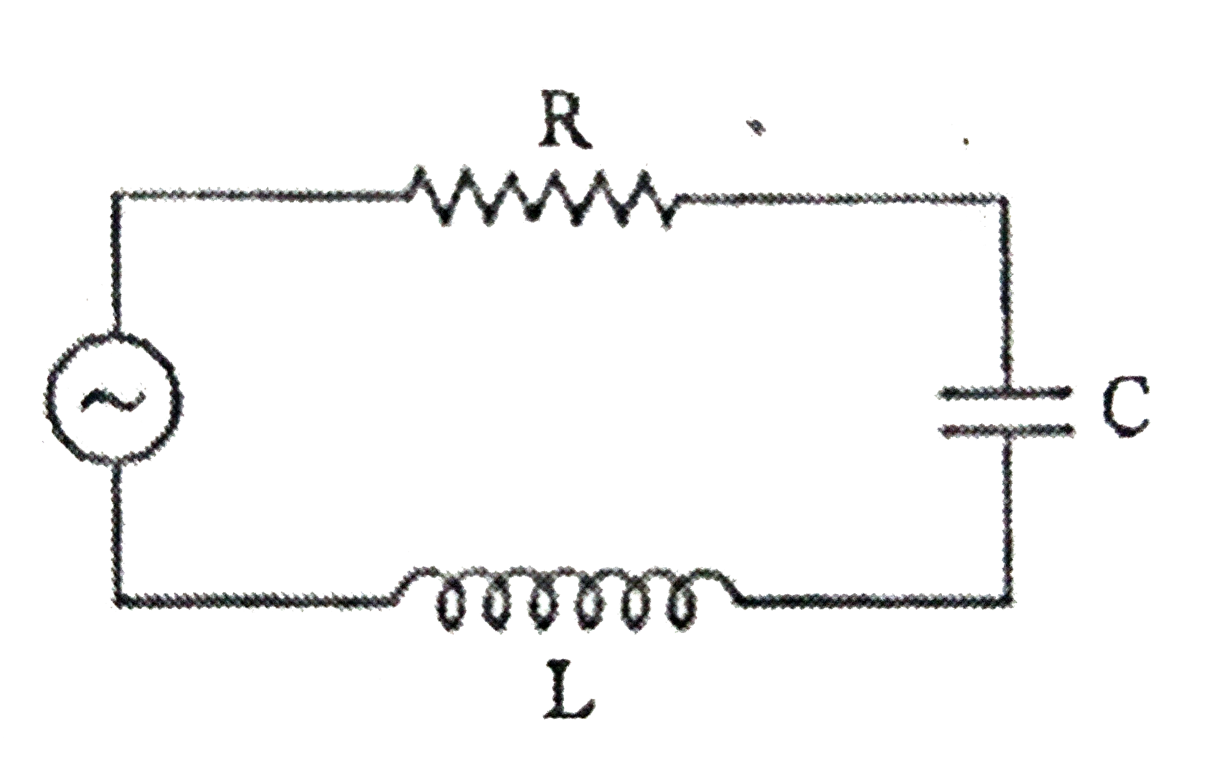
A series LCR circuit containing 5.0 H inductor, 80μF capacitor and 40Ω resistor is connected to 230 V variable frequency ac source. The angular frequencies of the source at which power transfered to circuit is half the power at resonant angular frequency are likely to be.
46 rad/s and 54 rad/s
42 rad/s and 58 rad/s
25 rad/s and 75 rad/s
50 rad/s and 25 rad/s
To solve the problem, we need to determine the angular frequencies at which the power transferred to the circuit is half of the power at the resonant angular frequency. Here’s a step-by-step breakdown of the solution:
Step 1: Identify the given values
- Inductance, L=5.0H
- Capacitance, C=80μF=80×10−6F
- Resistance, R=40Ω
- Voltage, V=230V
Step 2: Calculate the resonant angular frequency (ω0)
The resonant angular frequency for a series LCR circuit is given by the formula:
ω0=1√LC
Substituting the values:
ω0=1√5.0×80×10−6
Calculating LC:
LC=5.0×80×10−6=4.0×10⁻⁴
Now, calculate ω0:
ω0=1√4.0×10−4=10.02=50rad/s
Step 3: Determine the condition for power being half
The power transferred to the circuit is half of the maximum power at resonance when the current amplitude is I0√2. The relationship between power and current is:
P∝I2
Thus, if P=P0/2, then:
I=I0√2
Step 4: Calculate the bandwidth (Δω)
The bandwidth of the circuit can be calculated using the formula:
Δω=RL
Substituting the values:
Δω=405.0=8rad/s
Step 5: Find the angular frequencies (ω1 and ω2)
The angular frequencies at which the power is half of the maximum power are:
ω1=ω0−Δω2andω2=ω0+Δω2
Calculating ω1 and ω2:
ω1=50−82=50−4=46rad/s
ω2=50+82=50+4=54rad/s
Final Answer
The angular frequencies at which the power transferred to the circuit is half the power at the resonant angular frequency are ω1=46rad/s and ω2=54rad/s.
- Inductance, L=5.0H
- Capacitance, C=80μF=80×10−6F
- Resistance, R=40Ω
- Voltage, V=230V
The resonant angular frequency for a series LCR circuit is given by the formula:
ω0=1√LC
Substituting the values:
ω0=1√5.0×80×10−6
Calculating LC:
LC=5.0×80×10−6=4.0×10⁻⁴
Now, calculate ω0:
ω0=1√4.0×10−4=10.02=50rad/s
The power transferred to the circuit is half of the maximum power at resonance when the current amplitude is I0√2. The relationship between power and current is:
P∝I2
Thus, if P=P0/2, then:
I=I0√2
The bandwidth of the circuit can be calculated using the formula:
Δω=RL
Substituting the values:
Δω=405.0=8rad/s
The angular frequencies at which the power is half of the maximum power are:
ω1=ω0−Δω2andω2=ω0+Δω2
Calculating ω1 and ω2:
ω1=50−82=50−4=46rad/s
ω2=50+82=50+4=54rad/s
The angular frequencies at which the power transferred to the circuit is half the power at the resonant angular frequency are ω1=46rad/s and ω2=54rad/s.
Topper's Solved these Questions
Similar Questions
A series LCR circuit with L=4.0h,C=100μF and R=60Ω is connected to a varialbe frequency 240 V source. Calcalate
(i) angular frequency of the source which drives the circuit in resonace,
(ii) current at the resonating frequency,
(iii) rms potential drop across the inductro at resonance.
View SolutionFig. shows series LCR circuit with L=5.0H,C=80μF,R=40Ω connected to a variable frequency 240 V source. Calculate
(i) the angular freuquency of the source which drives the circuit at resonance.
(ii) Current at the resonanting frequency.
(iii) the rms pot. drop across the capacitor at resonance.

View Solution
Knowledge Check
An inductor 200 mH, capacitor 500μF and resistor 10Ω are connected in series with a 100 V variable frequency ac source. What is the frequency at which the power factor of the circuit is unity?
A10.22HzB12.4HzC19.2HzD15.9HzA 100 mH inductor, a 25μF capacitor and 15Ω resistoer are connected in series to a 120 V, 50Hz a.c source. Calculate the resonant frequency .
A100.7HzB100HzC100.2HzD1000HzFor an LCR series circuit with an aac source of angular frequency ω.
Acircular will be capacitive if ω>1√LCBcircular will be inductive if ω=1√LCCPower factor of circuit will be unity if capacitive reactance equals inductive reactanceDcircular will be leading voltage if ω>1√LC
A series LER circuit with C=80μF, L = 5.0 H and R=40Ω is connected to a variable frequency 240 V a.c. source Calculate
(i) angular frequency of the source which drives the circuit in resonanace.
(ii) current at the resonating frequency.
(iii) rms pot. drop across the capacitor.
View SolutionThe figure shows a series LCR circuit with L=10.0H2,C=40μF,R=60Ω connected to a variable frequency 240 V source. Calculate
(i) The angular frequency of the source which drives the circuit at resonance.
(ii) The current at the resonating frequency.
(iii) The rms potential drop across the capacitor at resonance.

View SolutionAn inductor 200 mH, capacitor 500 uF, resistor 10 Ω are connected in series with a 100 V variable frequency a.c. source. Calculate :
(i) frequency at which power factor in the circuit is unity,
(ii) current amplitude at this frequency,
(iii) Q-factor.
View SolutionA circuit containing a 20Ω resistor and 0.1μF capacitor in series is connected to 320 V ac supply of angular frequency 100 rad s−1. The impedance of the circuit is
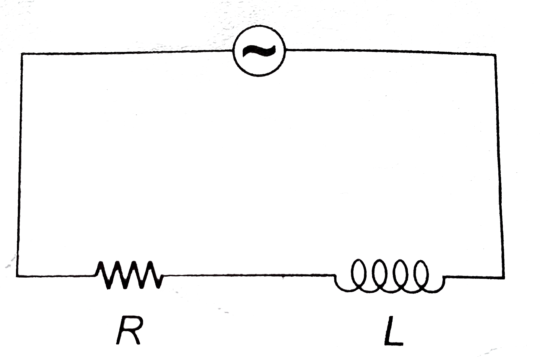
View SolutionIn the given LR circuit the source has angular frequency ω The power factore of the circuit is
 .
.
View Solution