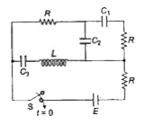
In the shown circuit, the switch is closed at time t=0. Initially all the capacitors were uncharged . The current through the cell, just after closing the switch is
E2R
E3R
ER
zero
The correct Answer is:A
At t=0, all the uncharged capacitors behave like short - circuit element and inductor like open circuit.
(Initially no current through C1 I=E/2R
Similar Questions
Knowledge Check
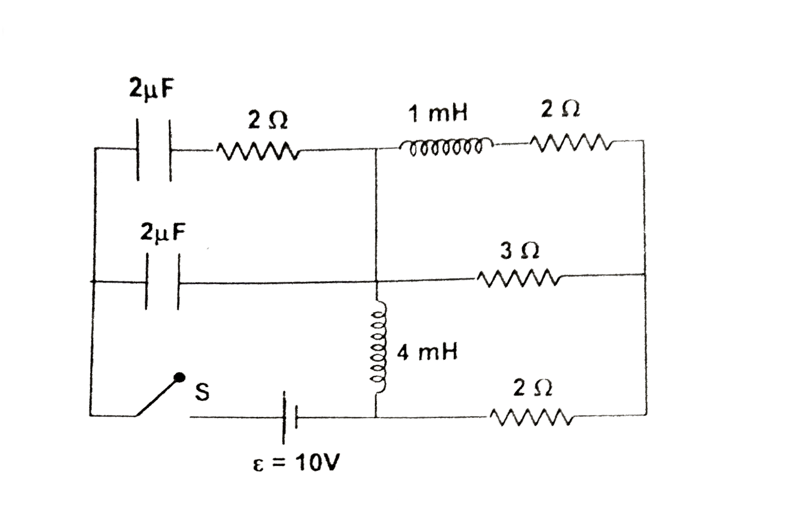
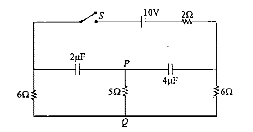
In the circuit shown, all the capacitors are initially uncharged. The current through the battery just after closing the switch 'S' isA2AB4AC5AD10AIn the circuit shown in figure, the capacitors are initially uncharged. The current through resistor PQ just after closing the switch is
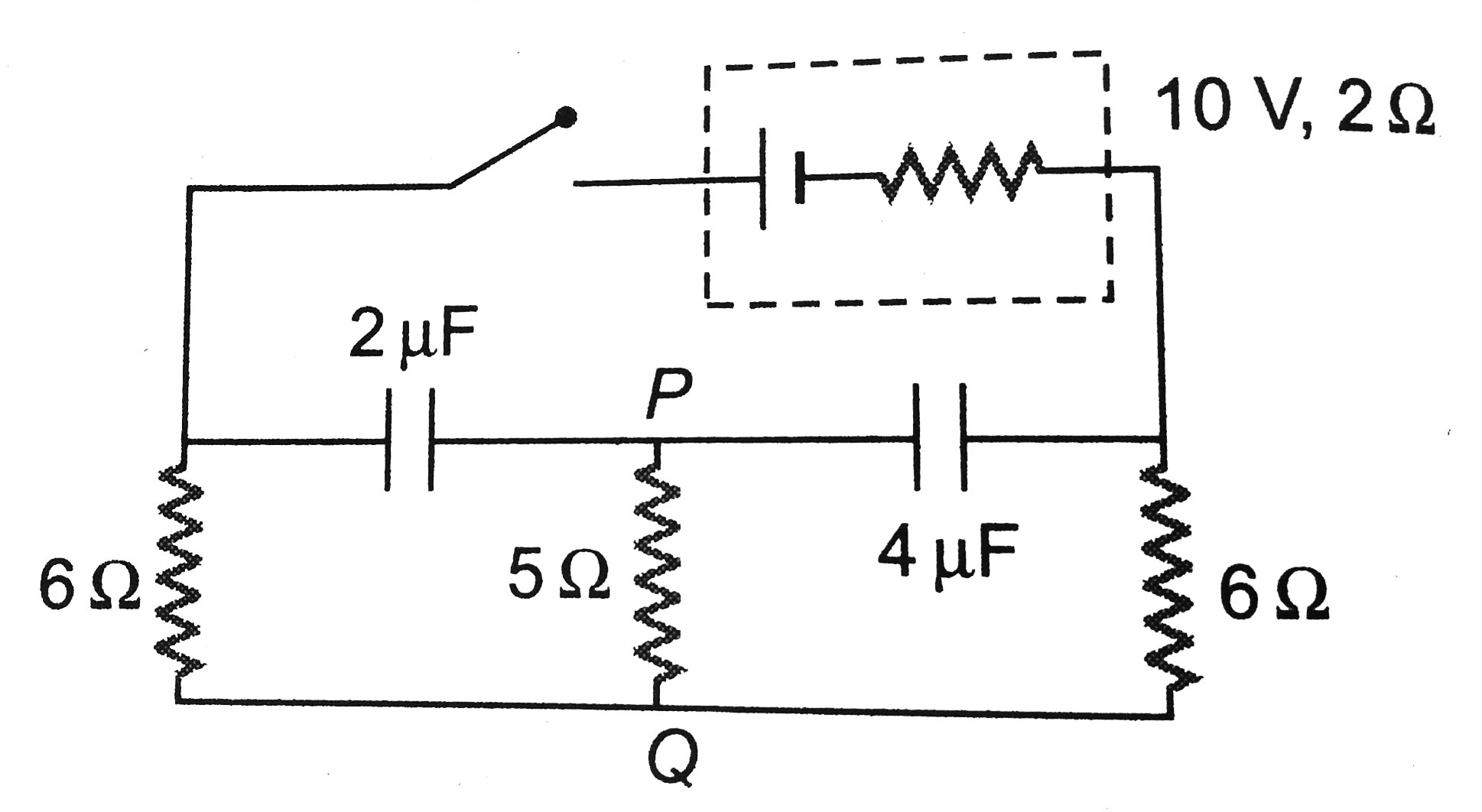 A2A from P to QB2A from Q to PC6A from P to QDzero
Initially the capacitor was uncharged Current in the capacitor just after switching on will be ?
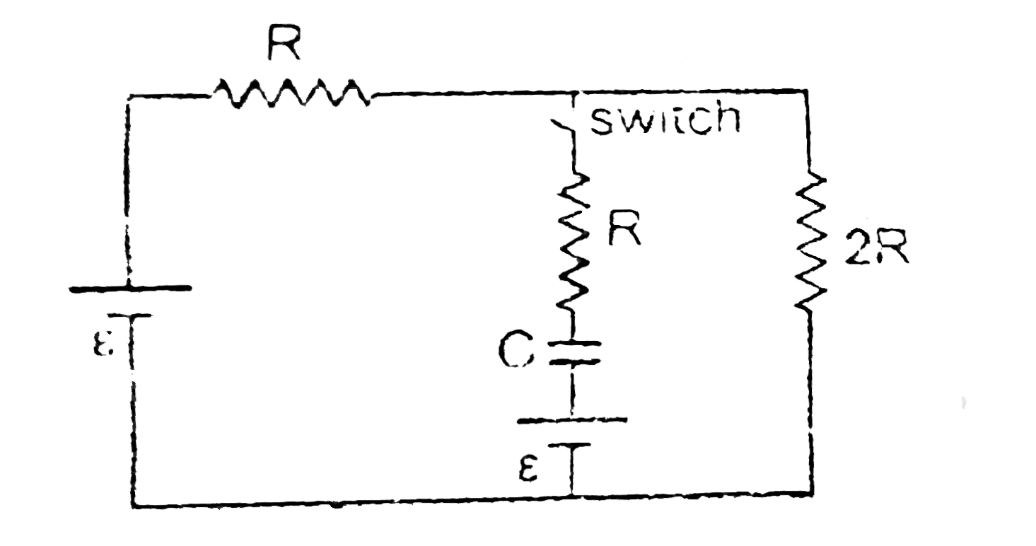 AεRBε2RCε5RDε4R
In the circuit shown in figure-3.351 the capacitors are initially uncharged. The current through resistor PQ just after closing the switch is :
View SolutionInitially the capacitor was uncharged Current in the capacitor just after switching on will be ?

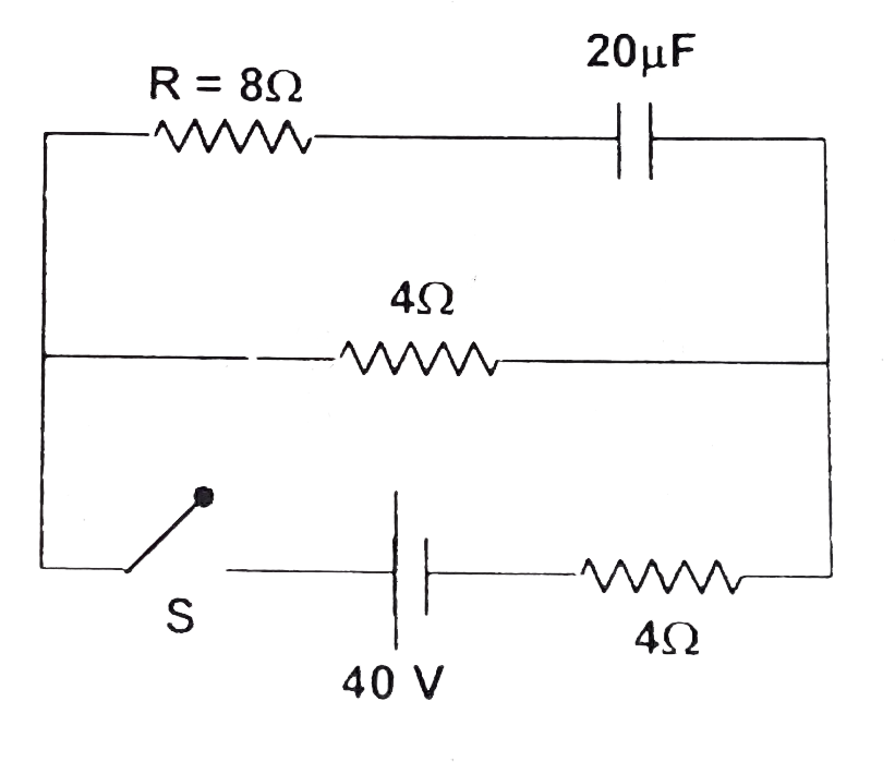
View SolutionIn the circuit shown, the switch 'S' is closed at t=0. Then capacitor is initially uncharged. Then the current through the resistor R=8Ω at t=0.4×10⁻³sec is (Take e−2=0.135 )
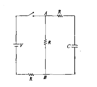
View SolutionIn the circuit shown in figure-3.244, the battery is an ideal one with emf V. The capacitor is initially uncharged. The switch S is closed at time t=0.
(a) Find the charge Q on the capacitor at time l
(b) Find the current in branch AB at time just after closing the switch.
View SolutionIn the circuit shown, the switch 'S' is closed at t=0. Then capacitor is initially uncharged. Then the current through the resistor R=8Ω at t=0.4×10⁻³sec is (Take e−2=0.135 )

View Solution
