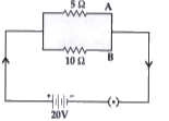
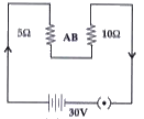
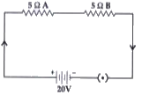
Two conductors A and B resistance 5ωand10ω respectively are first joined in parallel and then in series. In each case the voltage applied is 20 V.
Which of these circuit diagram shows the correct connection when A and B are joined in parallel?


none of these
The correct Answer is:A
To determine the correct circuit diagram that shows the connection when conductors A and B are joined in parallel, we can follow these steps:
1. Understanding Parallel Connections:
- In a parallel circuit, the voltage across each component is the same. Thus, if two resistors are connected in parallel, they share the same voltage across their terminals.
2. Identifying the Resistors:
- We have two resistors:
- Resistor A with a resistance of 5Ω
- Resistor B with a resistance of 10Ω
3. Voltage Applied:
- The voltage applied across the parallel connection is 20V.
4. Circuit Diagram for Parallel Connection:
- In a parallel configuration, both resistors A and B should be connected across the same two points (let's call them points C and D).
- This means that one terminal of resistor A is connected to point C and the other terminal to point D. The same applies to resistor B.
5. Visual Representation:
- The correct diagram will show both resistors connected to the same two nodes (C and D), indicating that they are in parallel.
- The current will divide between the two resistors, but the voltage across each will remain 20V.
6. Conclusion:
- After analyzing the provided options, the correct circuit diagram that shows the connection of A and B in parallel is the one where both resistors are connected across the same two points (C and D).
- In a parallel circuit, the voltage across each component is the same. Thus, if two resistors are connected in parallel, they share the same voltage across their terminals.
- We have two resistors:
- Resistor A with a resistance of 5Ω
- Resistor B with a resistance of 10Ω
- The voltage applied across the parallel connection is 20V.
- In a parallel configuration, both resistors A and B should be connected across the same two points (let's call them points C and D).
- This means that one terminal of resistor A is connected to point C and the other terminal to point D. The same applies to resistor B.
- The correct diagram will show both resistors connected to the same two nodes (C and D), indicating that they are in parallel.
- The current will divide between the two resistors, but the voltage across each will remain 20V.
- After analyzing the provided options, the correct circuit diagram that shows the connection of A and B in parallel is the one where both resistors are connected across the same two points (C and D).
Similar Questions
Two conductors A and B of resistances 5Ωand10Ω respectively are first joined in parallel and then in series. In each case the voltage applied is 20V.
(a) Draw the circuit diagram to show the combination of these conductors in each case.
(b) In which combination will the voltage across the conductors A and B be the same?
(c ) In which arrangement will the current through A and B is the same?
(d) Calculate the equivalent resistance for each arrangement.
View SolutionTwo resistors X and Y of resistances 2 ω and 3 ω respectively are first joined in parallel and then in series. In each case the voltage supplied is 5 V.
(i) Draw circuit diagrams to show the combination of resistors in each case.
(ii) Calculate the voltage across the 3 Q resistor in the series combination of resistors.
View Solution
Knowledge Check
Two conductors A and B resistance 5ωand10ω respectively are first joined in parallel and then in series. In each case the voltage applied is 20 V.
Equivalant resistance in parallel combination is:A15ωB3.33ωC0.3ωDNone of the aboveTwo conductors A and B resistance 5ωand10ω respectively are first joined in parallel and then in series. In each case the voltage applied is 20 V.
Equivalent resistance in series combination is:A15ωB3.33ωC0.3ωDNone of the aboveTwo conductors A and B resistance 5ωand10ω respectively are first joined in parallel and then in series. In each case the voltage applied is 20 V.
In which arrangment will the current through A and b be the same ?ASeries arrangmentBParallel arrangementCBoth of the aboveDNone of the above
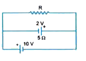
Two cells, of voltage 10 V and 2 V and internal resistances 10Ω and 5Ω respectively, are connected in parallel as shown in Fig. Find the effective voltage and effective resistance of the combination.

View SolutionThree resistors of 2Ω,3Ωand4Ω are connected in
(a) series
(b) parallel.
Find the equivalent resistance in each case.
View SolutionTwo cells of emfs 1.5 V and 2.0v having internal resistance 0.2Σ and 0.3 Σ respectively are connected in parallel . Calculate the emf and internal resistance of the equivalent cell .
View SolutionTwo cells of emfs 1.5 V and 2.0 V having internal resistances 0.2Ω and 0.3Ω respectively are connected in parallel. Calculate the emf and internal resistance of the equivalent cell.
View SolutionTwo conductors A and B resistance 5ωand10ω respectively are first joined in parallel and then in series. In each case the voltage applied is 20 V.
In which combination will the voltage across the conductors A and B be the same ?
View Solution
