The resistance of a metal rod of length 10 cm and rectangular cross-section of 1cm×12 connected to a battery across opposite faces is maximum when the battery is connected across.
10cm×12 cm faces
1cm×12cm cm faces
10cm×1 cm faces
10cm×12cm2 faces
The correct Answer is:C
To solve the problem, we need to determine the configuration that maximizes the resistance of the metal rod when connected to a battery.
Step 1: Understand the formula for resistance
The resistance R of a conductor is given by the formula:
R=ρLA
where:
- R is the resistance,
- ρ is the resistivity of the material,
- L is the length of the conductor,
- A is the cross-sectional area.
Step 2: Identify the dimensions of the rod
The rod has a length L=10cm and a rectangular cross-section of 1cm×12cm.
Step 3: Calculate the cross-sectional area
The cross-sectional area A can be calculated as:
A=width×height=1cm×12cm=12cm2
Step 4: Analyze the resistance
From the resistance formula, we see that:
- Resistance R is directly proportional to the length L of the rod.
- Resistance R is inversely proportional to the cross-sectional area A.
Step 5: Determine maximum resistance configuration
To maximize the resistance:
- We want the length L to be as long as possible (which is already given as 10 cm).
- We want the cross-sectional area A to be as small as possible.
Step 6: Conclusion
Since the cross-sectional area is fixed at 12cm2, the maximum resistance occurs when the battery is connected across the length of the rod. Therefore, the configuration that maximizes resistance is when the battery is connected across the longer dimension of the rod.
Final Answer
The resistance of the metal rod is maximum when the battery is connected across the length of the rod.
---
The resistance R of a conductor is given by the formula:
R=ρLA
where:
- R is the resistance,
- ρ is the resistivity of the material,
- L is the length of the conductor,
- A is the cross-sectional area.
The rod has a length L=10cm and a rectangular cross-section of 1cm×12cm.
The cross-sectional area A can be calculated as:
A=width×height=1cm×12cm=12cm2
From the resistance formula, we see that:
- Resistance R is directly proportional to the length L of the rod.
- Resistance R is inversely proportional to the cross-sectional area A.
To maximize the resistance:
- We want the length L to be as long as possible (which is already given as 10 cm).
- We want the cross-sectional area A to be as small as possible.
Since the cross-sectional area is fixed at 12cm2, the maximum resistance occurs when the battery is connected across the length of the rod. Therefore, the configuration that maximizes resistance is when the battery is connected across the longer dimension of the rod.
The resistance of the metal rod is maximum when the battery is connected across the length of the rod.
Topper's Solved these Questions
- SAMPLE PAPER 7BOOK - EDUCART PUBLICATIONCHAPTER - SAMPLE PAPER 7EXERCISE - SECTION-C
6 Videos
- SAMPLE PAPER 7BOOK - EDUCART PUBLICATIONCHAPTER - SAMPLE PAPER 7EXERCISE - SECTION-C
6 Videos
- SAMPLE PAPER 6BOOK - EDUCART PUBLICATIONCHAPTER - SAMPLE PAPER 6EXERCISE - Section-C
6 Videos
- SAMPLE PAPER 9 BOOK - EDUCART PUBLICATIONCHAPTER - SAMPLE PAPER 9 EXERCISE - SECTION - C
3 Videos
Similar Questions
Six identical resistance of resistance 20Ω each are connected in the form of a hexagon across a battery of 3 V. Find the current through the battery when the battery is connected (i) between any two adjacent vertices. (ii) across any two opposite vertices.
View SolutionA copper wire of length 50cm and area of cross-section 10−6m2 caries a current of 1A .If the resistivity of copper is 1.8×10⁻⁸Ωm .The electrical field across the wire is
View Solution
Knowledge Check
A metel rod of the length 10cm and a rectangular cross-section of 1 cm xx 1/2 cm is connected to a battery across opposite faces. The resistance will be
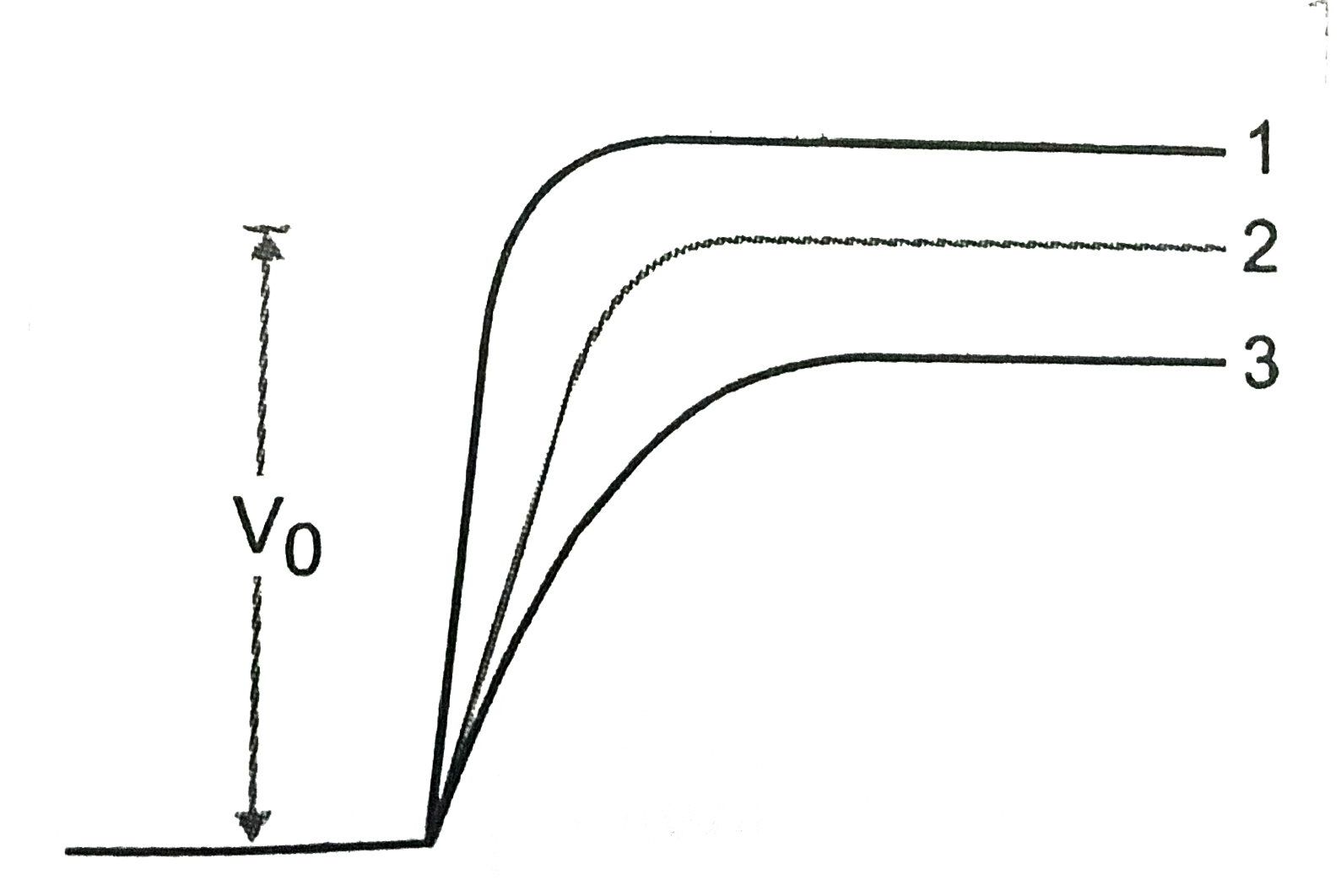
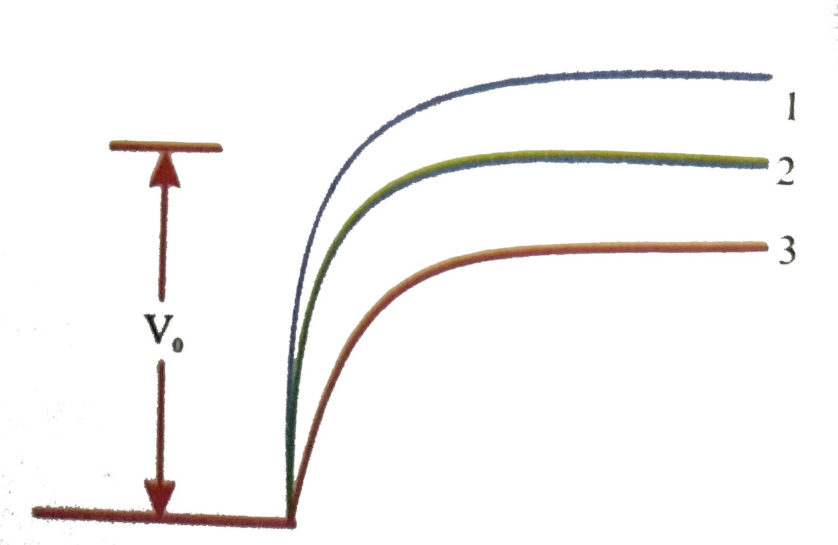
Amaximum when the battery is connected across 1cm×1/2 can facesBmaximum when the battery is connected across 10×1cm facesCmaximum when the battery is connected across 10 cm ×1/2 cm facesDsame irrespective of the three facesIn Fig . V0 is the potential barrier across a p-n junction, when no battery is connected across the junction
 A1 and 3 both correspond to forward bias of junctionB3 corresponds to forward bias of junction and 1 corresponds to reverse bias of junctionC1 corresponds to forward bias and 3 corresponds to reverse bias of junctionD3 and 1 both correspond to reverse bias of junction
In Fig. V0 is the potential barrier across a p−n junction, when no battery is connected across the junction :
 .A1 and 3 both correspond is forward bias of junctionB3 corresponds to forward bias of junction and 1 corresponds to reverse bias junctionC1 corresponds to forward bias and 3 corresponds to reverse bias junctionD3 and 1 both correspond to reverse bias and 3 corresponds to revers bias of junction
A wire of 50 cm long, 1mm2 in cross-section carries a current of 4 A, when connected to a 2 V battery, the resistivity of wire is
View SolutionA wire of 50 cm long, 1mm2 in cross-section carries a current of 4 A, when connected to a 2 V battery, the resistivity of wire is
View SolutionTwo coils of resistances 3Ωand6Ω are connected in series across a battery of emf12V. Find the electrical energy consumed in 1 minute in each resistance when these are connected in series.
View SolutionThe resistance of each arm of the wheat stone bridge is 10Ω. A resistance of 10Ω is connected in series with galvanometer then the equivalent resistance across the battery will be:-
View SolutionA galvanometer of resistance 10kΩ can measure a maximum current 1 mA. A non-ideal battery of emf 6 V is connected across this galvanometer. A resistance 1Ω is also connected across the galvanometer. If the galvanometer reads a current 0.2 mA, the internal resistance of the battery is:
View Solution
