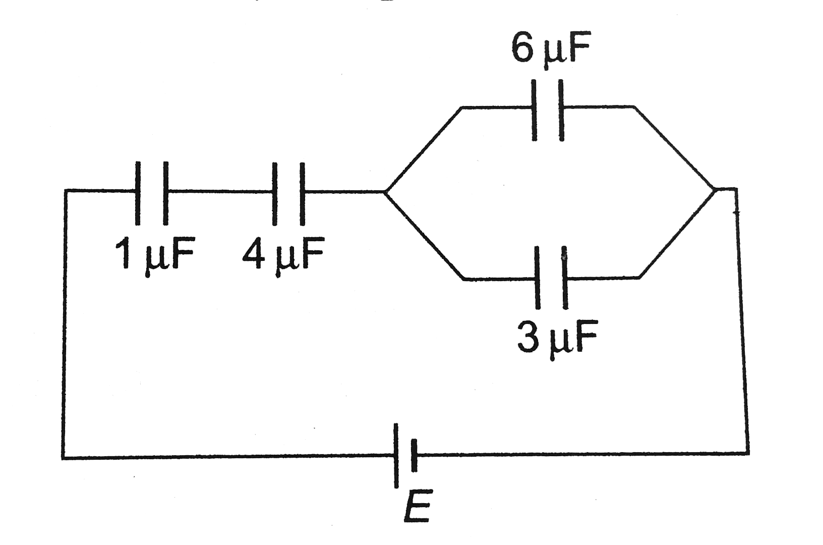
In the circuit shown in the figure, the potential difference across the 4.5μF capacitor is

The correct Answer is:4
Step by step video & image solution for In the circuit shown in the figure, the potential difference across the 4.5muF capacitor is by Physics experts to help you in doubts & scoring excellent marks in Class 12 exams.
Topper's Solved these Questions
- BOOK - AAKASH SERIESCHAPTER - CAPACITORS EXERCISE - LECTURE SHEET (EXERCISE - III) (LEVEL - I (MAIN)) (Straight Objective Type Questions )3videos
CAPACITORS
- BOOK - AAKASH SERIESCHAPTER - CAPACITORS EXERCISE - LECTURE SHEET (EXERCISE - III) (LEVEL - II (ADVANCED)) (More than one correct answer Type Questions )4videos
CAPACITORS
- BOOK - AAKASH SERIESCHAPTER - CAPACITORS EXERCISE - LECTURE SHEET (EXERCISE - II) (LEVEL - I (ADVANCED)) (Linked ComprehensionType Questions )7videos
CAPACITORS
- BOOK - AAKASH SERIESCHAPTER - ATOMSEXERCISE - PRACTICE EXERCISE21videos
ATOMS
- BOOK - AAKASH SERIESCHAPTER - COMMUNICATION SYSTEM EXERCISE - LECTURE SHEET (LEVEL - I) (MAIN) (EXERCISE - IV) (Straight Objective & More than one Correct Answer Type Questions)20videos
COMMUNICATION SYSTEM
Similar Questions
In the circuit shown in the figure, the potential difference across the 4.5μF capacitor is
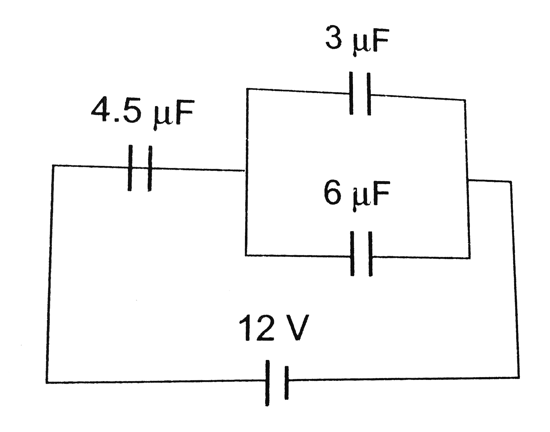 View Solution
In the adjoning figure, the potential difference across the 4.5μF capacitor is
 View Solution
In the circuit shown in figure potential difference across
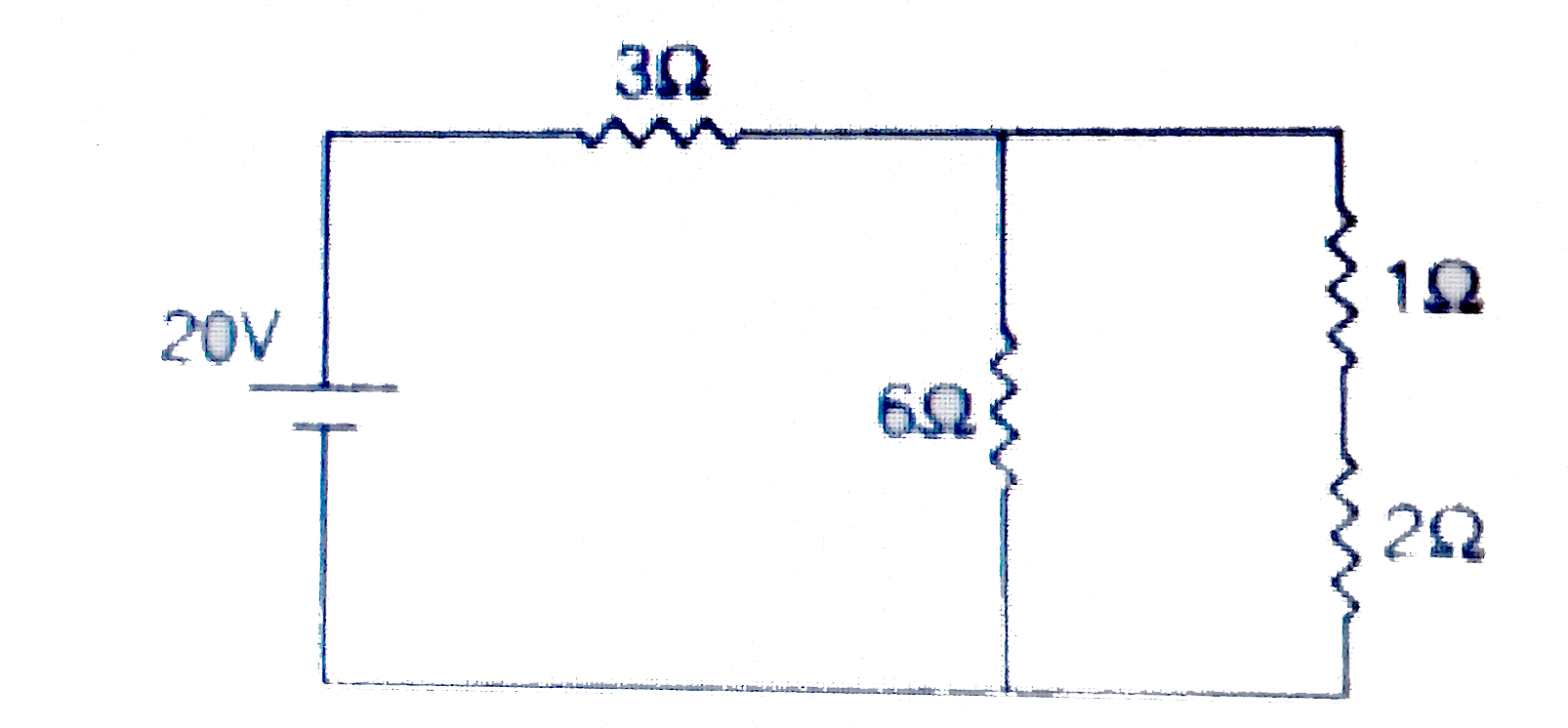 View Solution
Two capacitor of capacitance 2μFand3μF respectively are charged to potential difference 20 V each. Now the capacitors are connected such that the positively chargd plate of one capacitory is connected to the negatively charged plate of the other. after the current in the circuit has become negligible, the potential difference across the 2μF capacitor is ____V.
View SolutionIn the given circuit, with steady current, the potential difference across the capacitor is
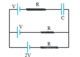 View Solution
In the network shown in given figure, find the potential difference across BD
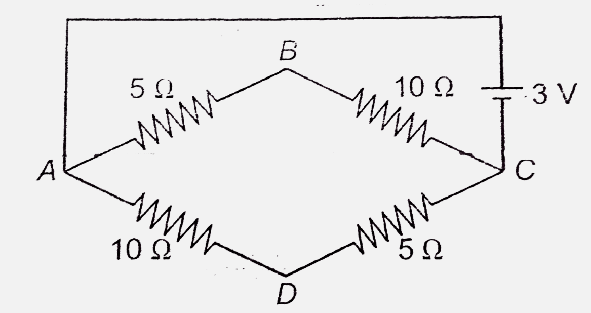 View Solution
given that potential differene across 1μF capacitor is 10V. Then,
 View Solution
If the power dissipated in the 27Ω resistor in the circuit shown is 108 watt, the potential difference across the 4Ω resistor is
View SolutionIn the given circuit, the potential difference across the 6μF capacitor in steady state is
 View Solution
A capacitor of capacity 2μF is changed to a potential different of 12V . It is then connected across an inductor of inductance 0.6mH What is the current in the circuit at a time when the potential difference across the capacitor is 6.0V ?
View Solution


