(A) : In case of M.C.G the torque on the coil is maximum in any position of the coil
(R) : In case of M.C.G the concave shaped magnetic poles render the field to be radial between them so that the plane of the coil is always parallel to the lines of induction even after deflection
Both 'A' and 'R' are true and 'R' is the correct explanation of 'A'.
Both 'A' and 'R' are true and 'R' is not the correct explanation of 'A'
'A' is true and 'R' is false
'A' is false and 'R' is false
The correct Answer is:A
To solve the given question, we need to analyze both the assertion (A) and the reason (R) provided in the context of a moving coil galvanometer (MCG).
1. Understanding the Assertion (A):
- The assertion states that in the case of a moving coil galvanometer, the torque on the coil is maximum in any position of the coil.
- In a moving coil galvanometer, the coil experiences torque due to the interaction of the magnetic field with the current flowing through the coil.
2. Torque Calculation:
- The torque (τ) on a coil in a magnetic field is given by the formula:
τ=n⋅i⋅A⋅B⋅sin(θ)
where:
- n = number of turns in the coil
- i = current flowing through the coil
- A = area of the coil
- B = magnetic field strength
- θ = angle between the magnetic field and the normal to the plane of the coil.
3. Maximum Torque Condition:
- The torque is maximum when sin(θ) is maximum, which occurs at θ=90° (i.e., when the plane of the coil is perpendicular to the magnetic field).
- However, the assertion claims that the torque is maximum in any position, which is not true. The torque is not maximum at all positions; it varies with the angle θ.
4. Conclusion on Assertion:
- Therefore, the assertion (A) is false.
5. Understanding the Reason (R):
- The reason states that the concave-shaped magnetic poles render the field to be radial between them, ensuring that the plane of the coil is always parallel to the lines of induction even after deflection.
- In a moving coil galvanometer, the concave-shaped poles do create a radial magnetic field, which means that the magnetic field lines are directed radially inward or outward from the poles.
6. Conclusion on Reason:
- The reason (R) is true because the radial magnetic field does help maintain the alignment of the coil with the magnetic field lines, but it does not imply that the torque is maximum at all positions.
7. Final Evaluation:
- Since the assertion is false and the reason is true, we conclude that both statements cannot be correct simultaneously.
Final Answer:
- Assertion (A) is false.
- Reason (R) is true.
- The assertion states that in the case of a moving coil galvanometer, the torque on the coil is maximum in any position of the coil.
- In a moving coil galvanometer, the coil experiences torque due to the interaction of the magnetic field with the current flowing through the coil.
- The torque (τ) on a coil in a magnetic field is given by the formula:
τ=n⋅i⋅A⋅B⋅sin(θ)
where:
- n = number of turns in the coil
- i = current flowing through the coil
- A = area of the coil
- B = magnetic field strength
- θ = angle between the magnetic field and the normal to the plane of the coil.
- The torque is maximum when sin(θ) is maximum, which occurs at θ=90° (i.e., when the plane of the coil is perpendicular to the magnetic field).
- However, the assertion claims that the torque is maximum in any position, which is not true. The torque is not maximum at all positions; it varies with the angle θ.
- Therefore, the assertion (A) is false.
- The reason states that the concave-shaped magnetic poles render the field to be radial between them, ensuring that the plane of the coil is always parallel to the lines of induction even after deflection.
- In a moving coil galvanometer, the concave-shaped poles do create a radial magnetic field, which means that the magnetic field lines are directed radially inward or outward from the poles.
- The reason (R) is true because the radial magnetic field does help maintain the alignment of the coil with the magnetic field lines, but it does not imply that the torque is maximum at all positions.
- Since the assertion is false and the reason is true, we conclude that both statements cannot be correct simultaneously.
- Assertion (A) is false.
- Reason (R) is true.
Topper's Solved these Questions
- MOVING CHARGES AND MAGNETISMBOOK - AAKASH SERIESCHAPTER - MOVING CHARGES AND MAGNETISMEXERCISE - EXERCISE-II
79 Videos
- MOVING CHARGES AND MAGNETISMBOOK - AAKASH SERIESCHAPTER - MOVING CHARGES AND MAGNETISMEXERCISE - EXERCISE-III
49 Videos
- MOVING CHARGES AND MAGNETISMBOOK - AAKASH SERIESCHAPTER - MOVING CHARGES AND MAGNETISMEXERCISE - EXERCISE-IA
142 Videos
- MOTION IN A STRAIGHT LINE BOOK - AAKASH SERIESCHAPTER - MOTION IN A STRAIGHT LINE EXERCISE - very Short answer type question
15 Videos
- NUCLEAR PHYSICSBOOK - AAKASH SERIESCHAPTER - NUCLEAR PHYSICSEXERCISE - ADDITIONAL PRACTICE PRACTICE SHEET (ADVANCED) Integer Type Questions
3 Videos
Similar Questions
(A) : Torque on the coil is always maximum, when coil is suspended in a radial magnetic field.
(R) : Torque depends upon the magnitude of the applied magnetic field.
View SolutionThe moving coil of a galvanometer 4 cm long and 1.5 cm wide, made of 200 turns of thin wire, works in a magnetic field with induction of 0.1 T. The plane of the coil is parallel to lines of induction. Find the torque acting on the coil when a current of 1 mA flows in it.
View SolutionA thermocol vessel contains 0.5kg of distilled water at 30∘C. A metal coil of area 5×10⁻³m2, number of turns 100, mass 0.06kg and resistance 1.6Ω is lying horizontally at the bottom of the vessel. A uniform time-varying magnetic field is set up to pass vertically through the coil at time t=0. The field is first increased from zero to 0.8T at a constant rate between 0 and 0.2s and then decreased to zero at the same rate between 0.2and0.4s. the cycle is repeated 12000 times. Make sketches of the current through the coil and the power dissipated in the coil as function of time for the first two cycles. Clearly indicate the magnitude of the quantities on the axes. Assumes that no heat is lost to the vessel or the surroundings. Determine the final tempreture of water under thermal equilibrium. Specific heat of metal =500jkg−1K−1 and the specific heat of water =4200jkg−1K−1. Neglect the inductance of coil.
View SolutionA rectangular coil of area 5.0×10⁻⁴m2 and 60 turns is pivoted about one of its vertical sides. The coil is in a radial horizontal field of 90 G (radial here means the field liners are in the plane of the coil for any rotation). What is the torsional constant of the hair spring connected to the coil if a current of 2.0 mA produces an angular deflection of 18∘?
View SolutionIn the given arrangement, the space between a pair of co-axial cylindrical conductors is evacuated. The outer cylinder, called anode, may be given a positive potential V relative to the inner cylinder.
A static homogeneous magnetic field →B parallel to the cylinder axis, directed out of plane of figure is aslo present. induced charges in the conductors are neglected.
We study the dynamics of electrons with rest mass m and charge e. The electrons are released at the surface of inner cylinder.
Consider the following two cases
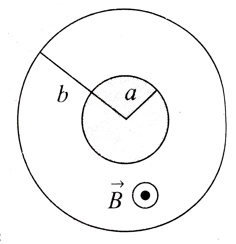
Case 1: Firstly the potential V is turned on, but →B=0. An electron with negligible velocity is ejected at the surface of inner cylinder. It is found to hit the anode.
Case 2: Now V = 0 but →B is present. An electron starts out with an initial velocity →v0 in radial direction. For magnetic field larger than critical value Bc the electron will not reach the anode.
The critical magnetic field Bc is given by
View SolutionIn the given arrangement, the space between a pair of co-axial cylindrical conductors is evacuated. The outer cylinder, called anode, may be given a positive potential V relative to the inner cylinder.
A static homogeneous magnetic field →B parallel to the cylinder axis, directed out of plane of figure is aslo present. induced charges in the conductors are neglected.
We study the dynamics of electrons with rest mass m and charge e. The electrons are released at the surface of inner cylinder.
Consider the following two cases
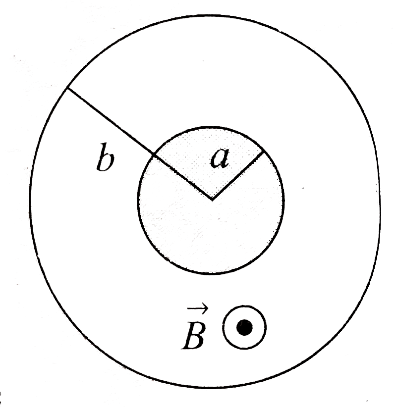
Case 1: Firstly the potential V is turned on, but →B=0. An electron with negligible velocity is ejected at the surface of inner cylinder. It is found to hit the anode.
Case 2: Now V = 0 but →B is present. An electron starts out with an initial velocity →v0 in radial direction. For magnetic field larger than critical value Bc the electron will not reach the anode.
Considering case 2, the trajectory of electron will be
View SolutionIn the given arrangement, the space between a pair of co-axial cylindrical conductors is evacuated. The outer cylinder, called anode, may be given a positive potential V relative to the inner cylinder.
A static homogeneous magnetic field →B parallel to the cylinder axis, directed out of plane of figure is aslo present. induced charges in the conductors are neglected.
We study the dynamics of electrons with rest mass m and charge e. The electrons are released at the surface of inner cylinder.
Consider the following two cases
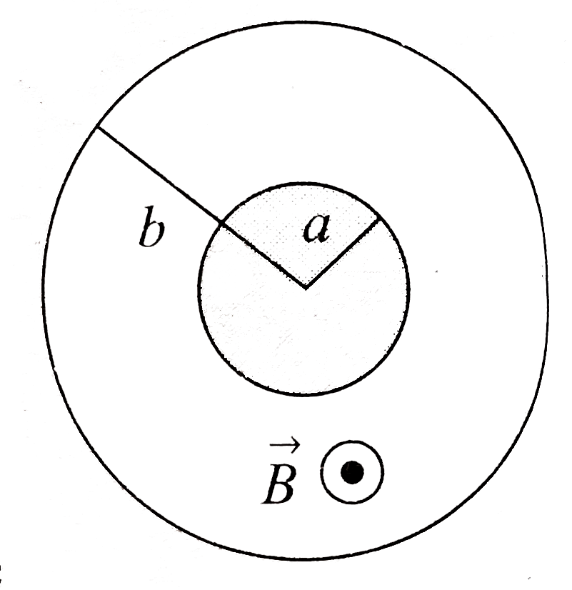
Case 1: Firstly the potential V is turned on, but →B=0. An electron with negligible velocity is ejected at the surface of inner cylinder. It is found to hit the anode.
Case 2: Now V = 0 but →B is present. An electron starts out with an initial velocity →v0 in radial direction. For magnetic field larger than critical value Bc the electron will not reach the anode.
Considering the case 1, the trajectory of electron will be
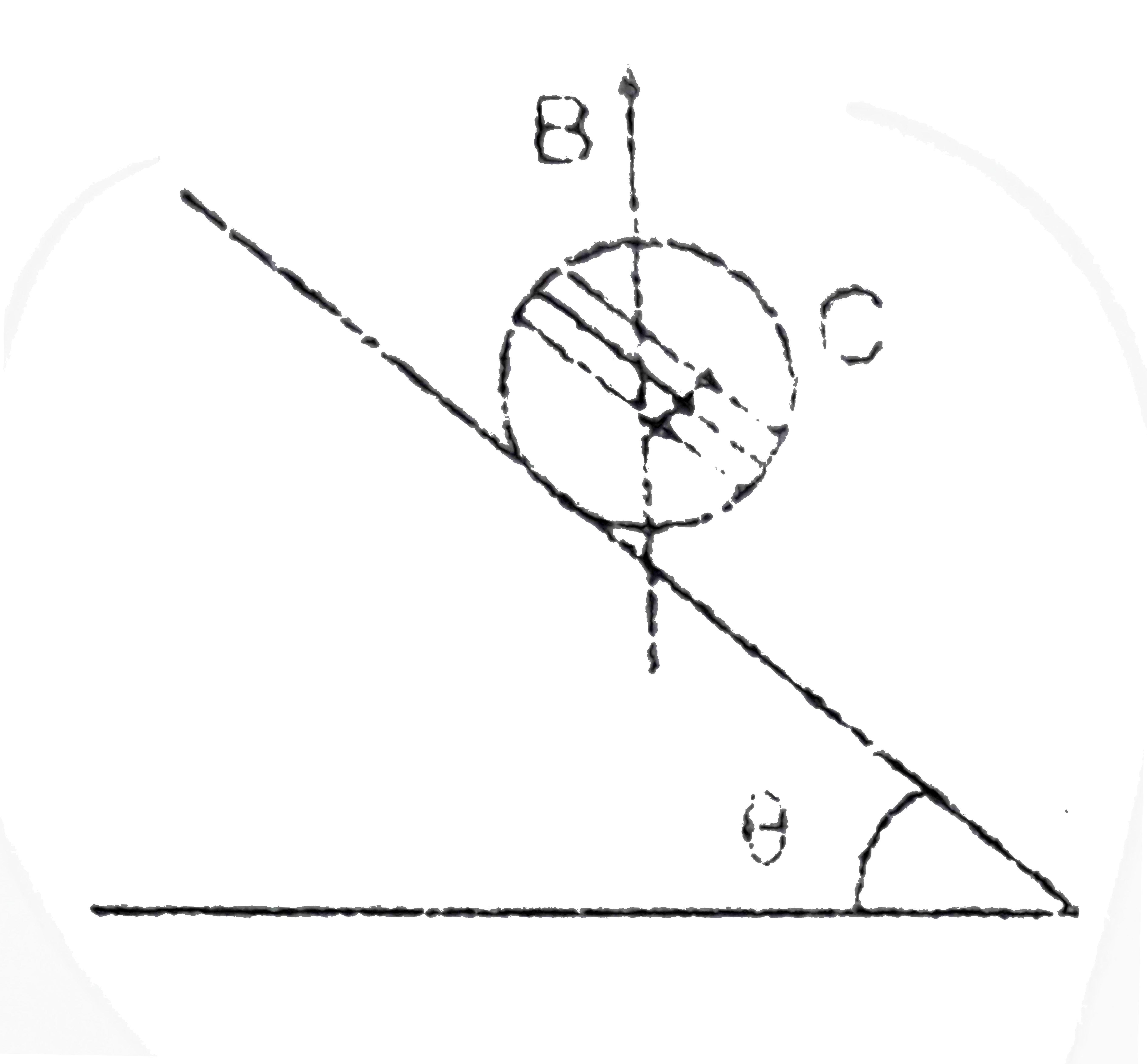
View SolutionFigure shows (only cross section) a wooden cylinder C with a mass m of 0.25kg,a radius R and a length l perpenducular to the plane of paper of 0.1meter with N=10 where N is number of turns of wire loop contains the axis of the cylinder the least current through the loop is P2A that will prevent the cylinder from moving down a plane whose surface is inclined at angle θ to the horizontal, in the presence of a vertical field of magnetic induction 0.5weber/meter2, if the planer of the windings is parallel to the inclinded plane?(bottom most point of cylinder does not slip)then find value of P.
View SolutionIt is desired to measure the magnitude of field between the poles of a powerful loud speaker magnet. A small flat search coil of area 2cm2 with 25 closely wound turns is positioned normal to the field direction and then quickly snatched out of the field region (Equivalently, one can give it a quick 90∘ turn to bring its plane parallel to the field direction). The total charge flowing in the coil (mesured by a ballistic galbanometer connected to the coil) is 7.5 mC. The resistance of the coil and galvanometer is 0.5Ω. Estimate the field strength of the magnet.
View SolutionA dc motor works on the principle that a current carrying coil, when placed in a magnetic field experiences a torque. The arrangement consists of a coil suspended in a region of magnetic field. When a current is passed through the coil, it experiences torque and starts rotating. A simple arrangement is shown below.
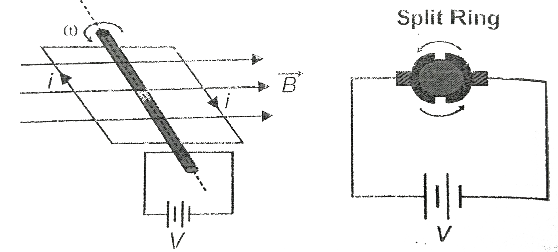
The coil rotates under the action of torque. The current is supplied to the coil by an arrangement of two sliding contacts and a split ring. As the coil rotates, the magnetic flux linked with the coil changes. This leads to production of an induced emf ε in the coil. By Lenz's law, the induced emf opposes the applied voltage and therefore, it is called back emf. If R is the resistance in the coil, the current i flowing through the coil at any instant is i=V−εR. The back emf is developed due to induction and it is directly proportional to speed of rotation and it is directly proportional to speed of rotation of the motor. There is a continuous power loss i2R in the motor, in form of heat.
When a dc motor is running unloaded (full speed) the current through it is 1 A. What will be the current flowing through the motor, when it is loaded to run at half its maximum speed, it applied voltage is 10 V and armature resistance is 5Ω
View Solution
