(A) : Voltmeter put across a part of the circuit, it reads slightly less than the original voltage.
(R) : Voltmeter is always connected in parallel in circuit across which voltage is to be measured.
Both 'A' and 'R' are true and 'R' is the correct explanation of 'A'.
Both 'A' and 'R' are true and 'R' is not the correct explanation of 'A'
'A' is true and 'R' is false
'A' is false and 'R' is false
The correct Answer is:B
To solve the question, we need to analyze both the assertion (A) and the reason (R) provided:
Step 1: Understand the Assertion (A)
The assertion states that "Voltmeter put across a part of the circuit, it reads slightly less than the original voltage."
- Analysis: This statement is generally true. When a voltmeter is connected across a part of a circuit, it can read a voltage that is slightly less than the actual voltage due to its internal resistance. This is because the voltmeter itself draws some current, which can affect the voltage across the component it is measuring.
Step 2: Understand the Reason (R)
The reason states that "Voltmeter is always connected in parallel in the circuit across which voltage is to be measured."
- Analysis: This statement is true. A voltmeter is designed to measure the potential difference (voltage) across two points in a circuit, and it must be connected in parallel to do so. This is a fundamental principle of how voltmeters operate.
Step 3: Determine the Relationship Between A and R
Now we need to determine if the reason (R) correctly explains the assertion (A).
- Analysis: While both A and R are true, R does not explain why A is true. The reason for the voltmeter reading slightly less than the original voltage is due to its internal resistance affecting the circuit, not merely because it is connected in parallel.
Conclusion
- Final Assessment:
- Assertion (A) is true.
- Reason (R) is true.
- However, R is not the correct explanation for A.
Thus, the correct answer is that both A and R are true, but R is not the correct explanation of A.
Answer
Both A and R are true, but R is not the correct explanation of A.
---
The assertion states that "Voltmeter put across a part of the circuit, it reads slightly less than the original voltage."
The reason states that "Voltmeter is always connected in parallel in the circuit across which voltage is to be measured."
Now we need to determine if the reason (R) correctly explains the assertion (A).
- Final Assessment:
- Assertion (A) is true.
- Reason (R) is true.
- However, R is not the correct explanation for A.
Both A and R are true, but R is not the correct explanation of A.
Topper's Solved these Questions
- MOVING CHARGES AND MAGNETISMBOOK - AAKASH SERIESCHAPTER - MOVING CHARGES AND MAGNETISMEXERCISE - EXERCISE-II
79 Videos
- MOVING CHARGES AND MAGNETISMBOOK - AAKASH SERIESCHAPTER - MOVING CHARGES AND MAGNETISMEXERCISE - EXERCISE-III
49 Videos
- MOVING CHARGES AND MAGNETISMBOOK - AAKASH SERIESCHAPTER - MOVING CHARGES AND MAGNETISMEXERCISE - EXERCISE-IA
142 Videos
- MOTION IN A STRAIGHT LINE BOOK - AAKASH SERIESCHAPTER - MOTION IN A STRAIGHT LINE EXERCISE - very Short answer type question
15 Videos
- NUCLEAR PHYSICSBOOK - AAKASH SERIESCHAPTER - NUCLEAR PHYSICSEXERCISE - ADDITIONAL PRACTICE PRACTICE SHEET (ADVANCED) Integer Type Questions
3 Videos
Similar Questions
Assertion : Voltmeter is connected in parallel with the circuit
Reason : Resistance of a voltmeter is very large.
View Solution(A) : The resistance of voltmeter is very small as compared to the resistance of the galvanometer, from which it is obtained.
(R) : The voltmeter is connected in series to the conductor across which potential difference is to be measured.
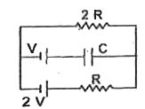
View SolutionIn the circuit shown, tp across the 2R resistor muhe voltage drost be

View SolutionAn ammeter, voltmeter and a resistor are connected in series to a cell and the readings are noted as I and V. If another resistor R is connected in parallel with a voltmeter, then
View SolutionWhy is ammeter connected in series and voltmeter in parallel in the circuit?
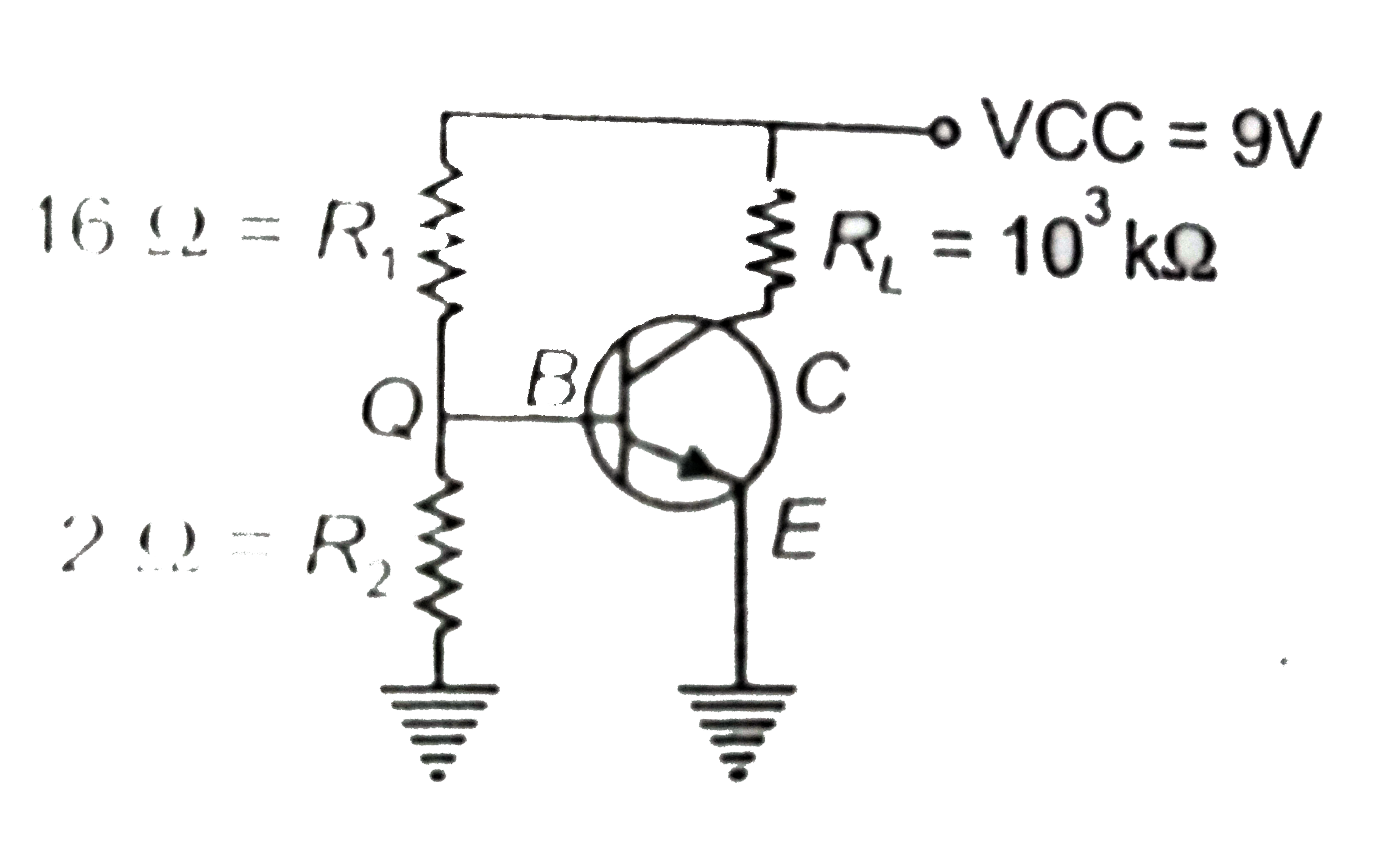
View SolutionIn the given circuit , the voltage across the base emitter junction is

View SolutionHow is voltmeter connected in the circuit to measure potential difference between two points ?
View SolutionFor the circuit shown in figure, determine the voltage across 4Ω resistors in volt ?

View SolutionCan the peak voltage across the inductor be greater than the peak voltage of the source in an LCR circuit?
View SolutionA voltmeter of resistance R1 and an ammeter of resistance R2 are connected in series across a battery oif negligible internal resistance. When as resistance R is connected in parallel to voltmeter reading of ammeter increases three times white that of voltmeter reduces to one third. Find the ratio of R1 and R2.
View Solution
