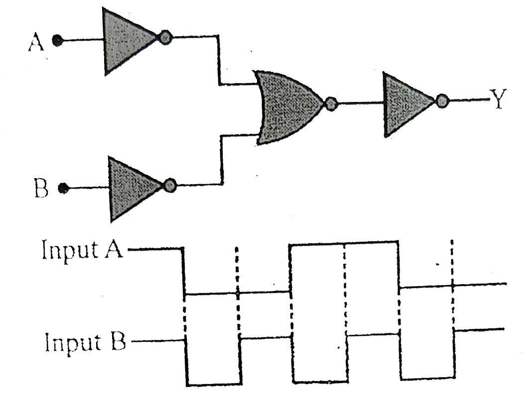
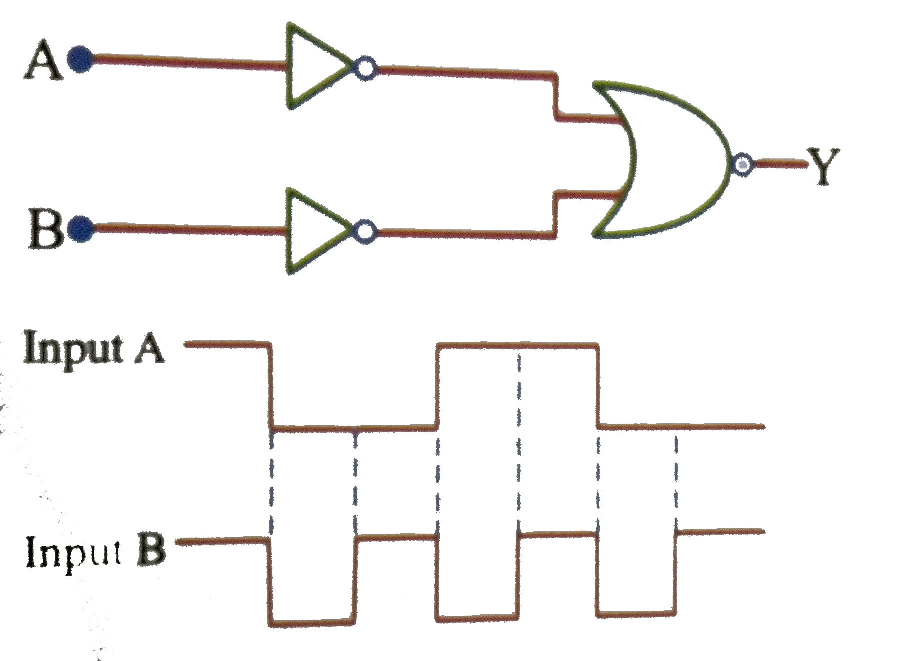
The logic circuit shown below has the input waveforems 'A' and 'B' as shown. Pick out the correct output waveform
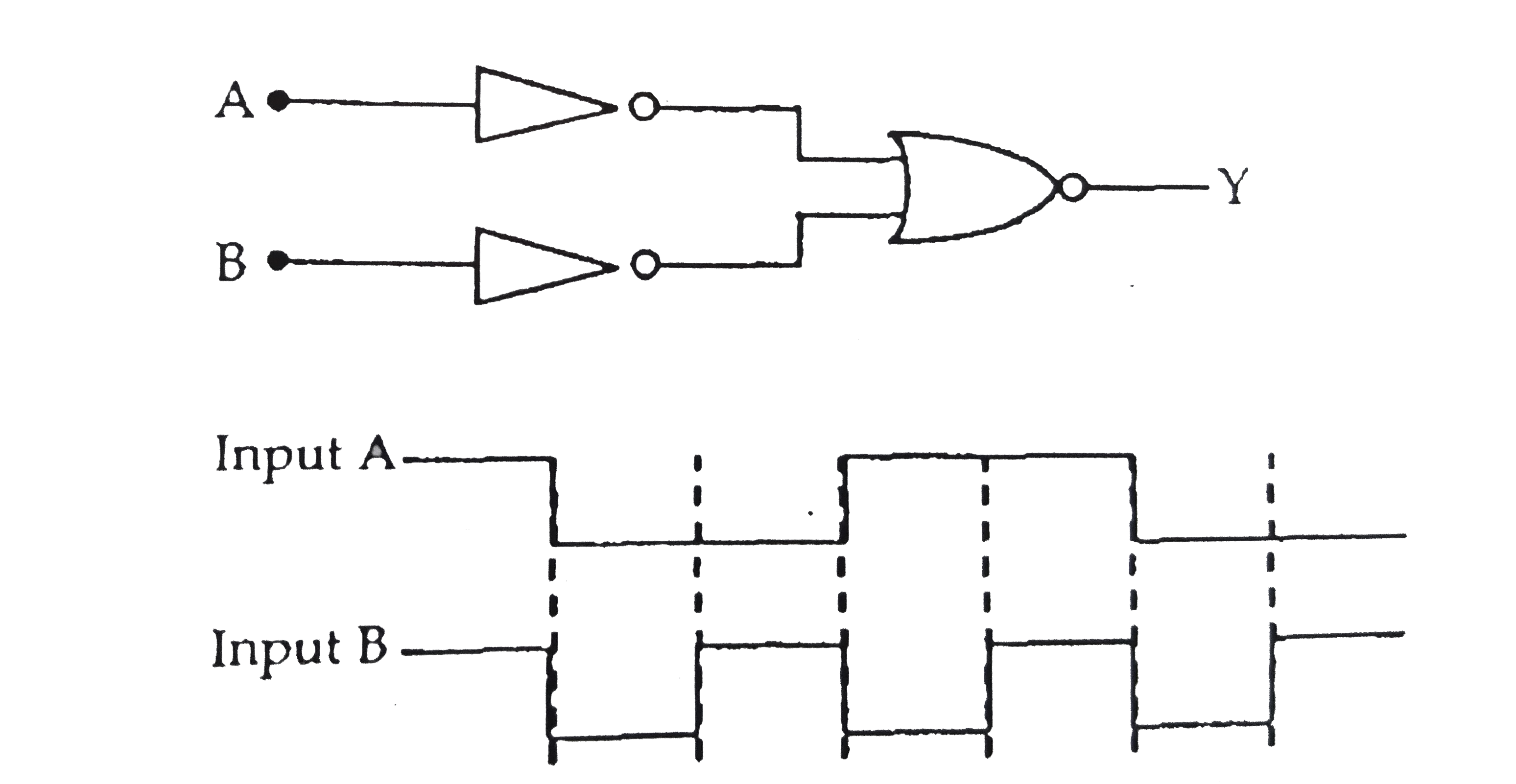


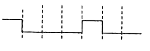
The correct Answer is:D
Step by step video & image solution for The logic circuit shown below has the input waveforems 'A' and 'B' as shown. Pick out the correct output waveform by Physics experts to help you in doubts & scoring excellent marks in Class 12 exams.
Topper's Solved these Questions
- BOOK - AAKASH SERIESCHAPTER - SEMICONDUCTOR DEVICESEXERCISE - PRACTICE EXERCISE (ENERGY BANDS AND CLASSIFICATION OF SOLIDS )31videos
SEMICONDUCTOR DEVICES
- BOOK - AAKASH SERIESCHAPTER - SEMICONDUCTOR DEVICESEXERCISE - PRACTICE EXERCISE (TRANSISTORS )8videos
SEMICONDUCTOR DEVICES
- BOOK - AAKASH SERIESCHAPTER - SEMICONDUCTOR DEVICESEXERCISE - EXERCISE -II (TRANSISTORS )9videos
SEMICONDUCTOR DEVICES
- BOOK - AAKASH SERIESCHAPTER - RAY OPTICSEXERCISE - PROBLEMS ( LEVEL-II)60videos
RAY OPTICS
- BOOK - AAKASH SERIESCHAPTER - UNITS AND MEASUREMENTEXERCISE - PRACTICE EXERCISE45videos
UNITS AND MEASUREMENT
Similar Questions
Knowledge Check
- Question 1 - Select One
The logic circuit shown below has the input waveforems 'A' and 'B' as shown. Pick out the correct output waveform
 A
A B
B C
C D
D
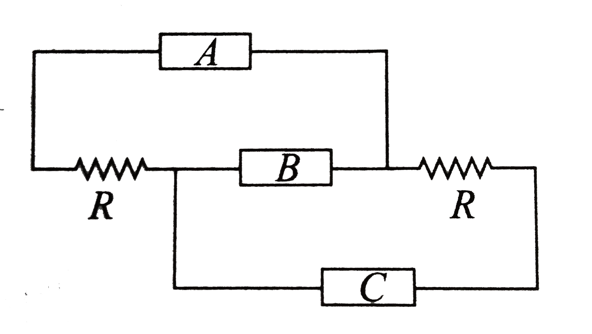
A circuit is shown below.
 View Solution
For the logic circuit shown the truth table is
 View Solution
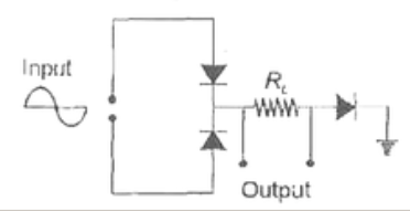
In the circuit shown , the input waveform is given. Which of the following correctly gives the output wavefrorm across RL?
 View Solution
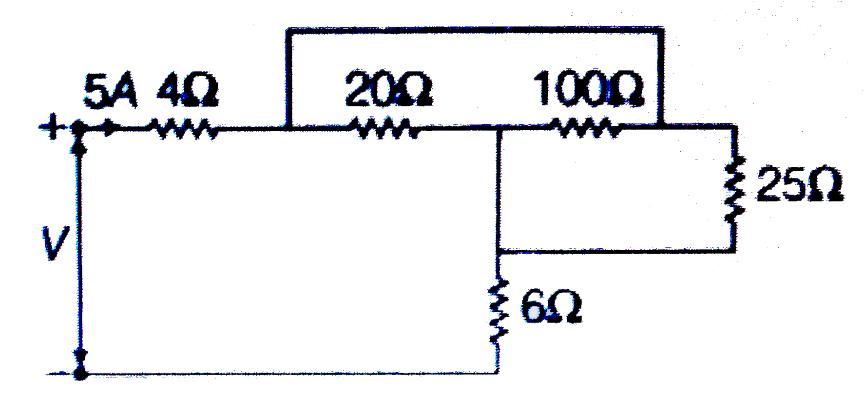
In the circuit shown below, V should be:
 View Solution
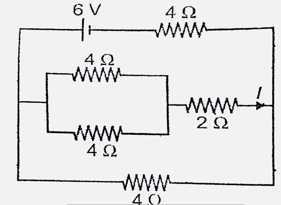
The current l in the circuit shown below is
 View Solution
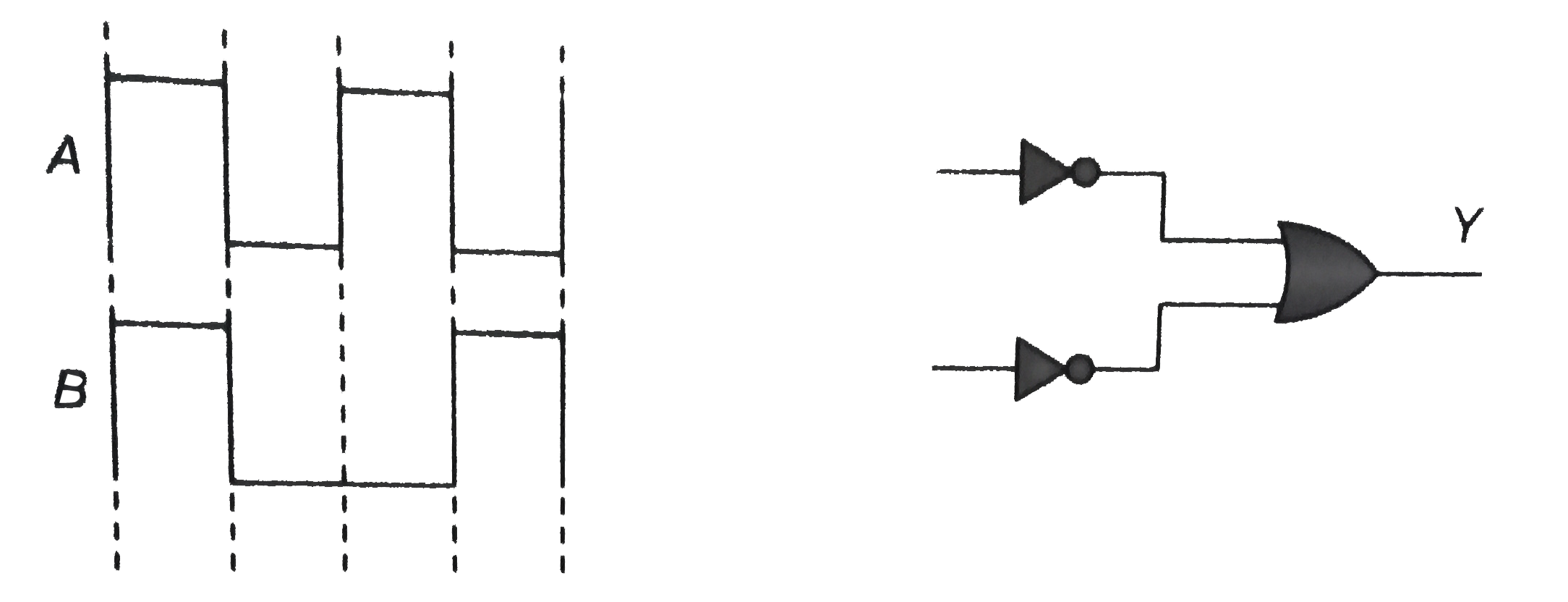
In the given circuit as shown the two input waveform A and B are applied simultaneously. The resultant waveform Y is
 View Solution
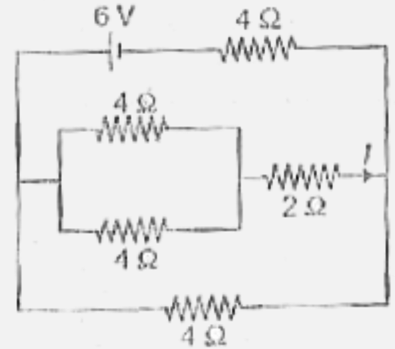
The current I in the circuit shown below is
 View Solution


 .
.