A full wave rectifier circuit along with the output is shown in figure. The contribution (s) from the diode 1 is (are):
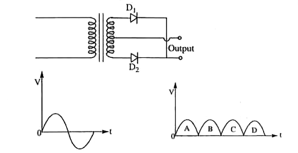
C
A,C
B,D
A,B,C,D
The correct Answer is:B
Step by step video & image solution for A full wave rectifier circuit along with the output is shown in figure. The contribution (s) from the diode 1 is (are): by Physics experts to help you in doubts & scoring excellent marks in Class 12 exams.
Topper's Solved these Questions
- BOOK - AAKASH SERIESCHAPTER - SEMICONDUCTOR DEVICESEXERCISE - PRACTICE EXERCISE (TRANSISTORS )8videos
SEMICONDUCTOR DEVICES
- BOOK - AAKASH SERIESCHAPTER - SEMICONDUCTOR DEVICESEXERCISE - PRACTICE EXERCISE (LOGIC GATES )15videos
SEMICONDUCTOR DEVICES
- BOOK - AAKASH SERIESCHAPTER - SEMICONDUCTOR DEVICESEXERCISE - EXERCISE -II (LOGIC GATES)12videos
SEMICONDUCTOR DEVICES
- BOOK - AAKASH SERIESCHAPTER - RAY OPTICSEXERCISE - PROBLEMS ( LEVEL-II)60videos
RAY OPTICS
- BOOK - AAKASH SERIESCHAPTER - UNITS AND MEASUREMENTEXERCISE - PRACTICE EXERCISE45videos
UNITS AND MEASUREMENT
Similar Questions
A full wave rectifier circuit along with the input and output are shown in the figure. The contribution from the diode D2 is (are)
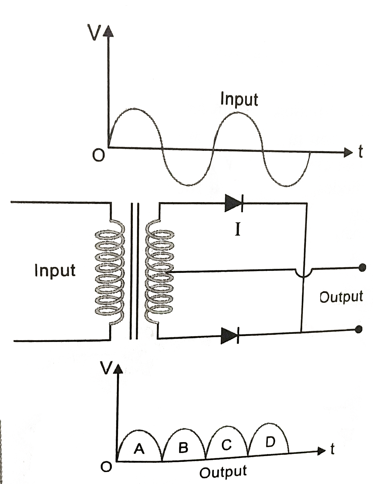
View SolutionA full wave rectifier circuit along with the input and output are shown in Fig. the concentrations from the diode I is (are)
 View Solution
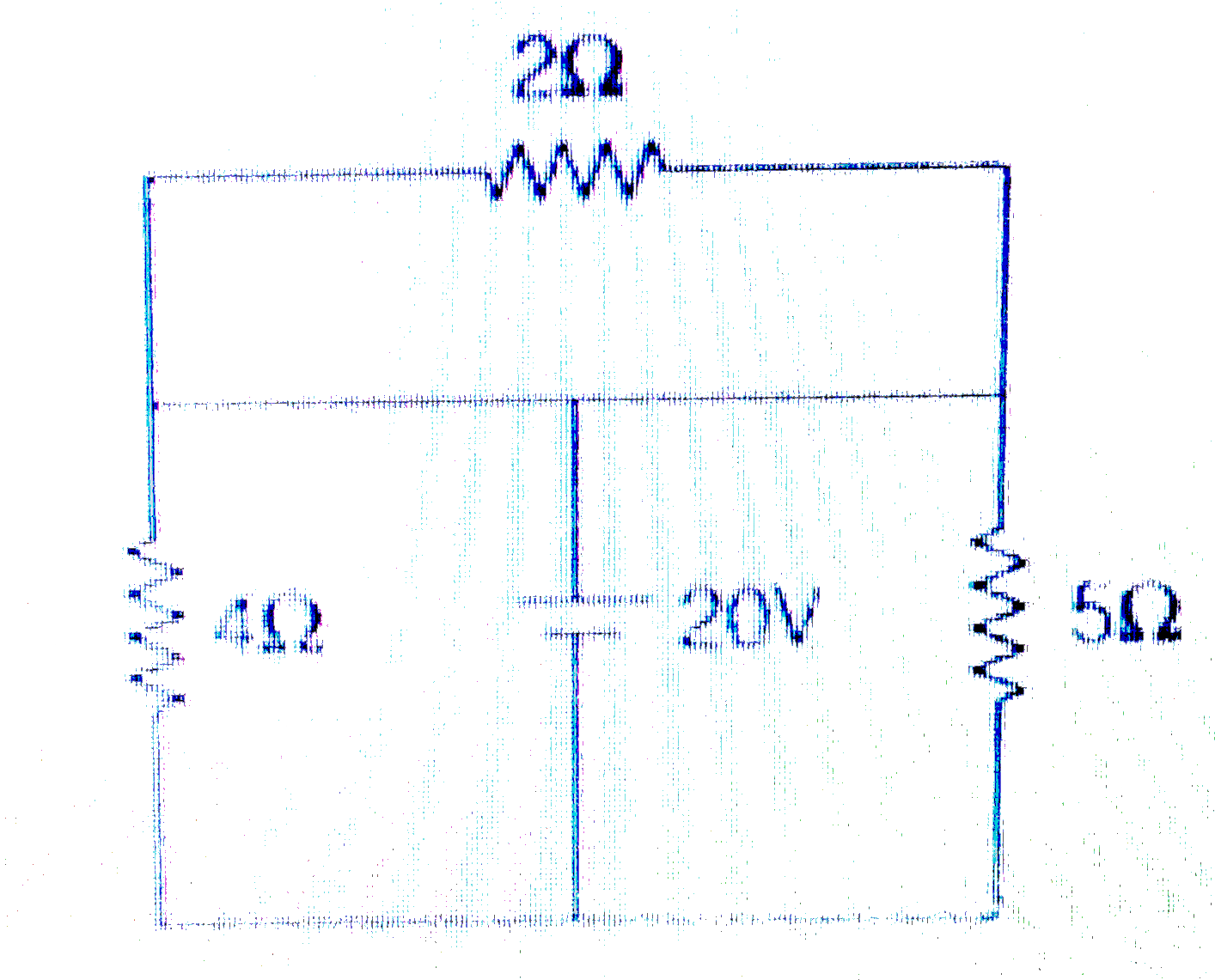
In the circuit shown in figure
 View Solution
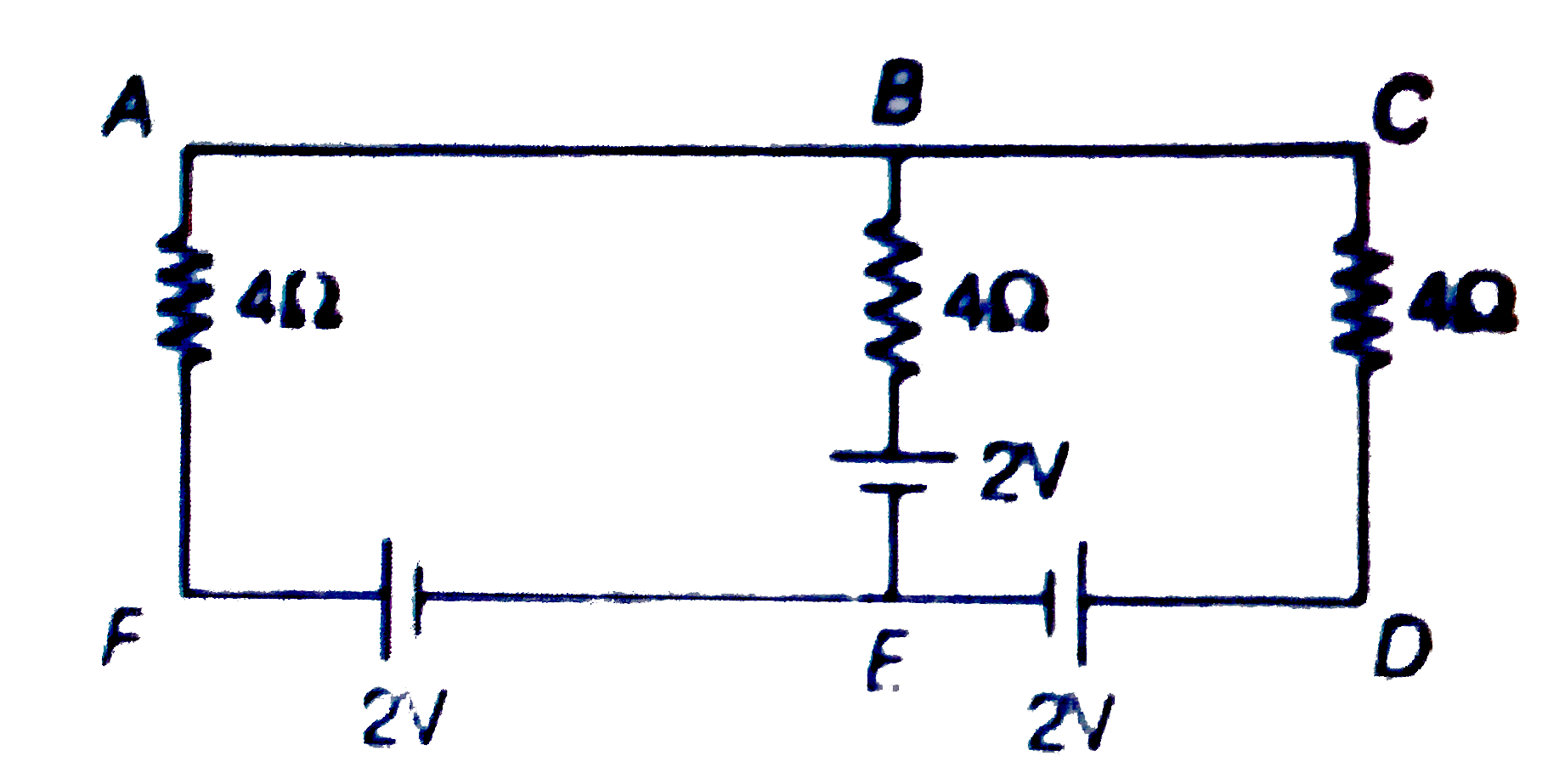
In the circuit shown in figure
 View Solution
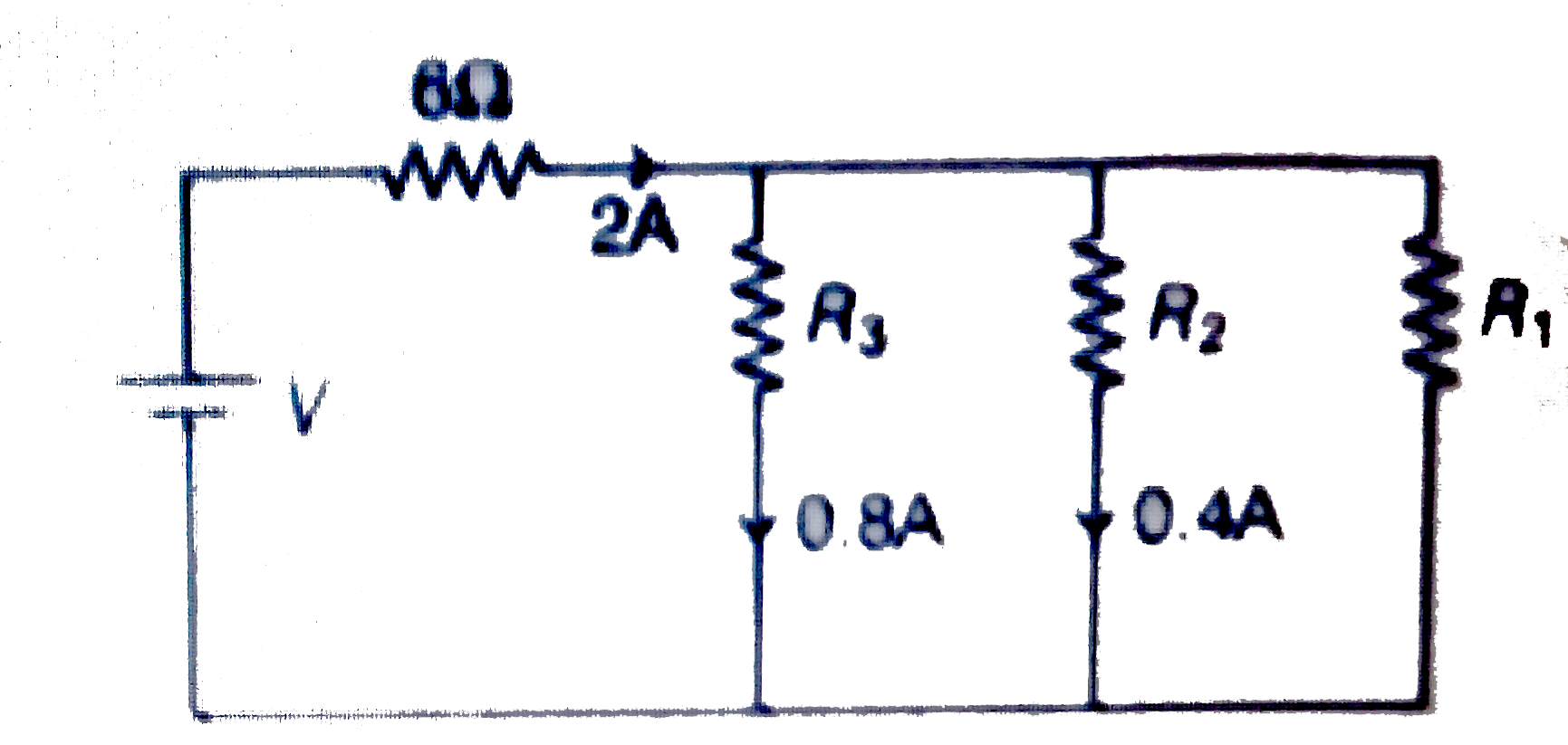
In the circuit shown in figure
 View Solution
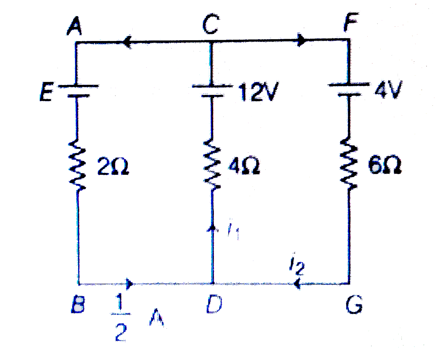
In the circuit shown in figure
 View Solution
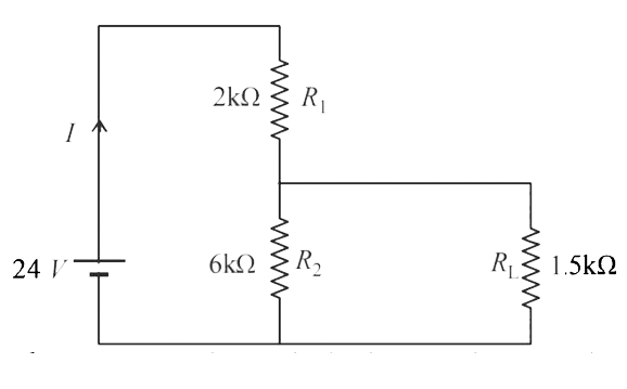
For the circuit shown in figure
 View Solution
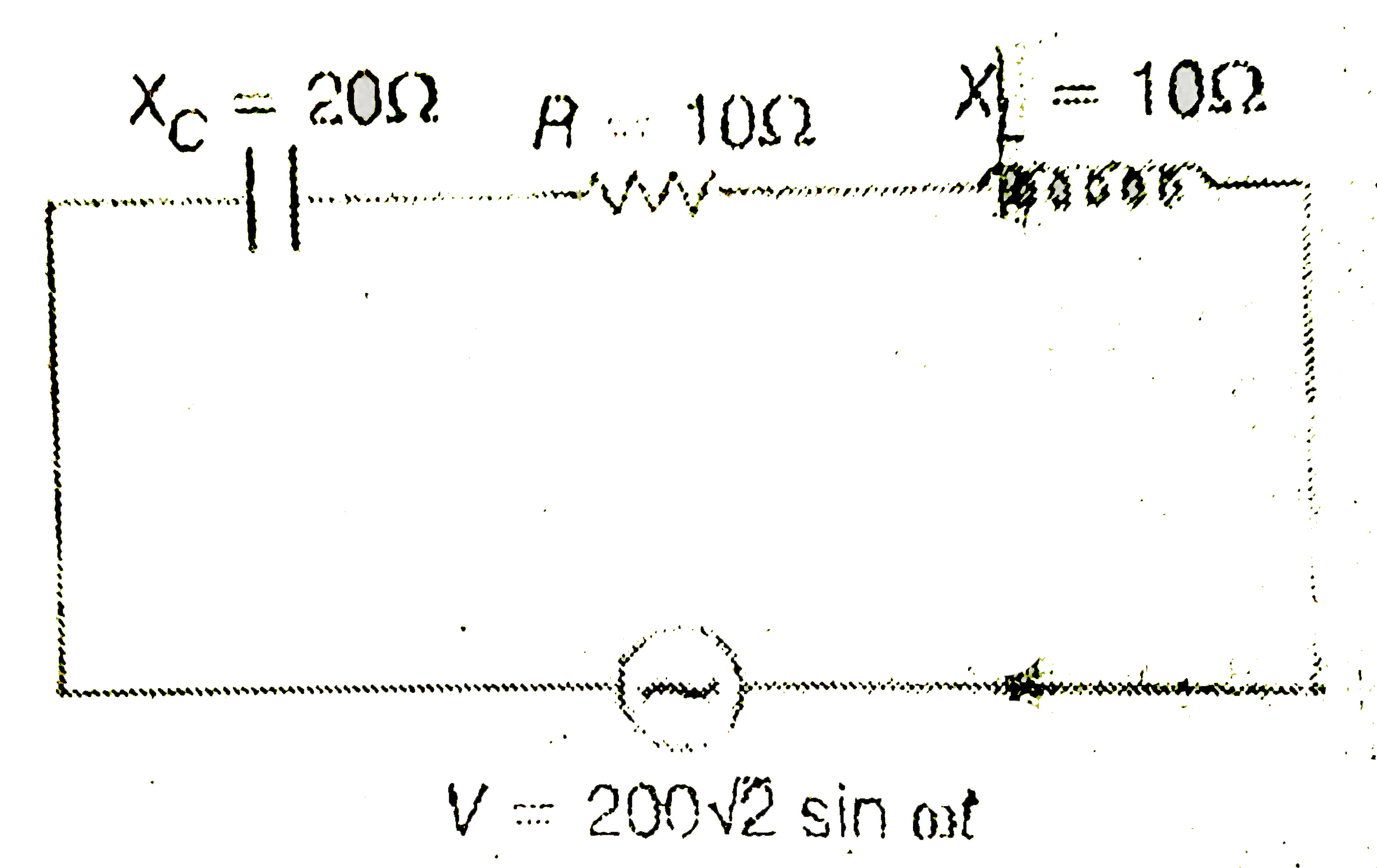
In LCR circuit as shown in figure
 View Solution
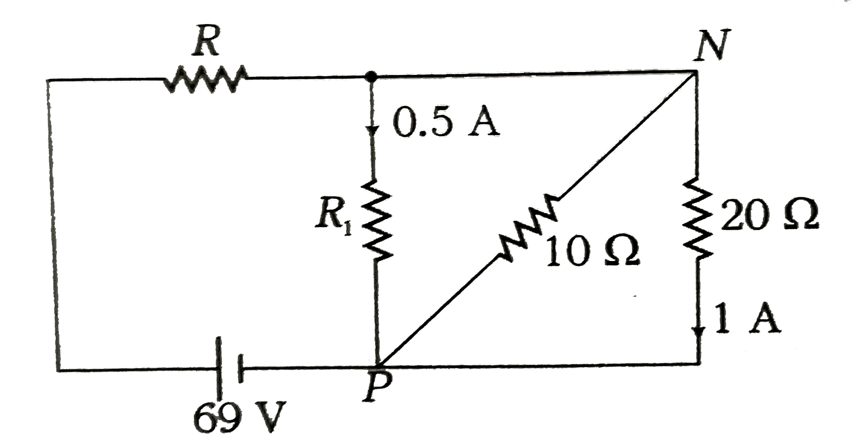
In the circuit shown in the figure,
 View Solution
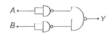
Output Y of the gate shown in figure
 View Solution

