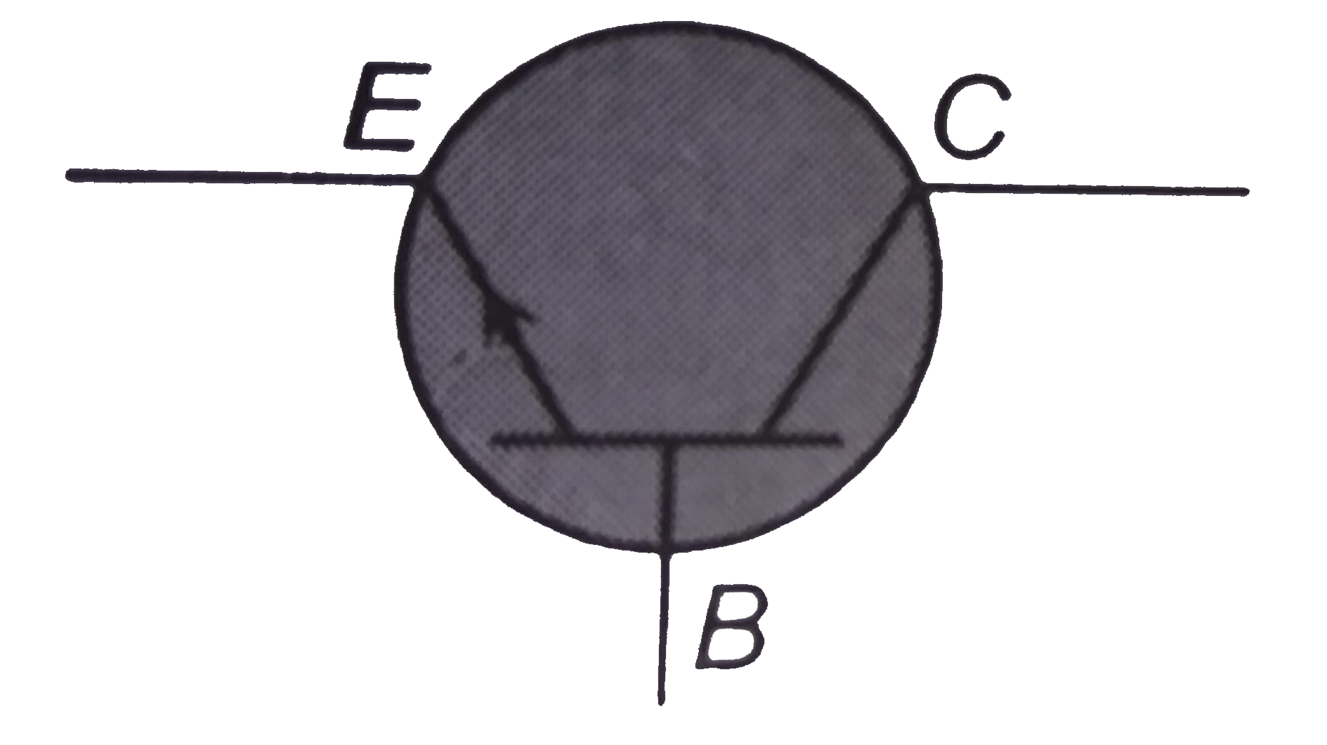
The logic symbol shown in figure represents

NOT gate
OR gate
NAND gate
NOR gate
The correct Answer is:A
Step by step video & image solution for The logic symbol shown in figure represents by Physics experts to help you in doubts & scoring excellent marks in Class 12 exams.
Topper's Solved these Questions
- BOOK - AAKASH SERIESCHAPTER - SEMICONDUCTOR DEVICESEXERCISE - PROBLEMS41videos
SEMICONDUCTOR DEVICES
- BOOK - AAKASH SERIESCHAPTER - SEMICONDUCTOR DEVICESEXERCISE - EXERCISE - IA54videos
SEMICONDUCTOR DEVICES
- BOOK - AAKASH SERIESCHAPTER - SEMICONDUCTOR DEVICESEXERCISE - PRACTICE EXERCISE (TRANSISTORS )8videos
SEMICONDUCTOR DEVICES
- BOOK - AAKASH SERIESCHAPTER - RAY OPTICSEXERCISE - PROBLEMS ( LEVEL-II)60videos
RAY OPTICS
- BOOK - AAKASH SERIESCHAPTER - UNITS AND MEASUREMENTEXERCISE - PRACTICE EXERCISE45videos
UNITS AND MEASUREMENT
Similar Questions
Knowledge Check
- Question 1 - Select One
The I-V characteristics shown in the figure represents
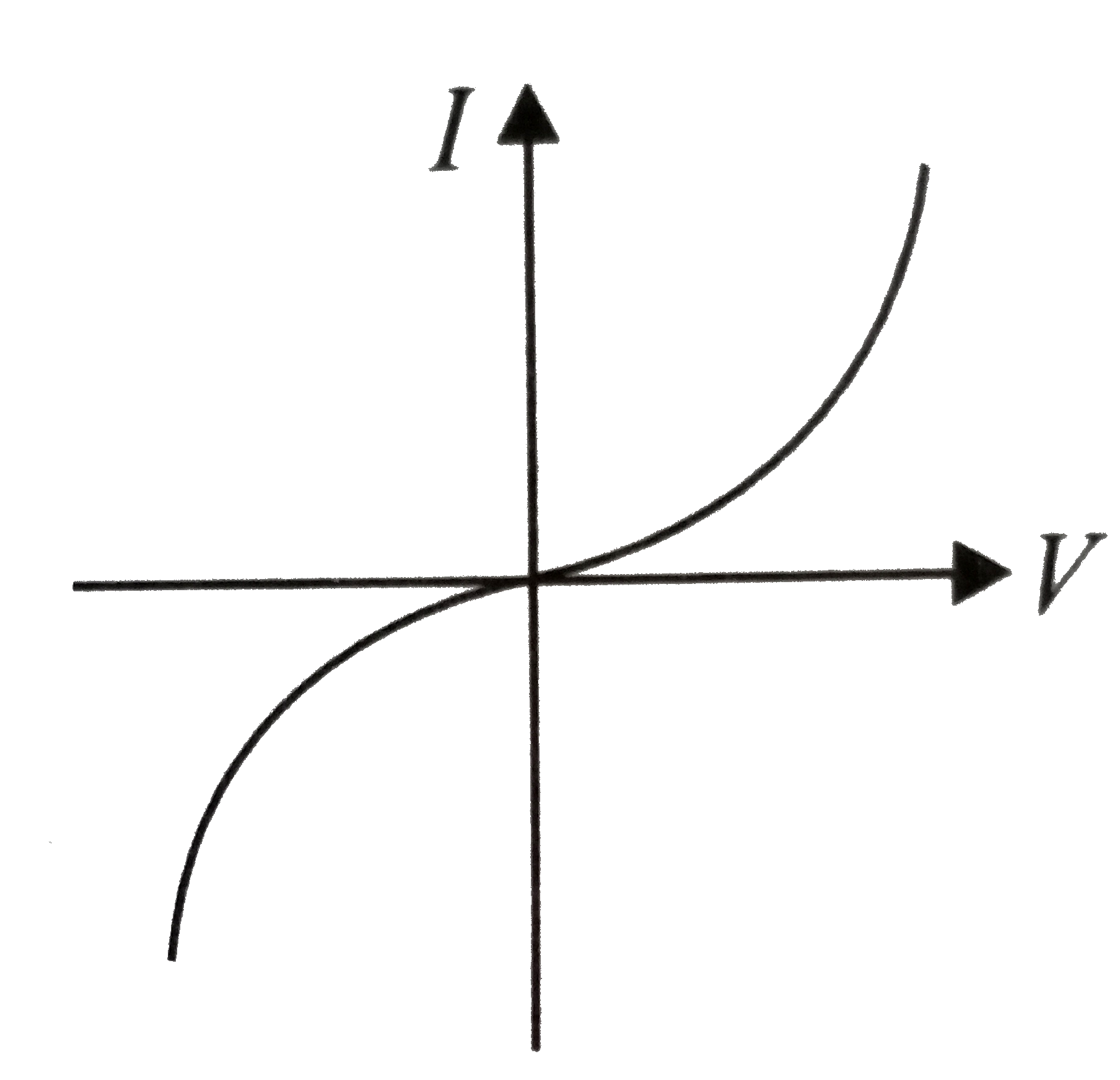 Aohmic conductorsBnon-ohmic conductorsCinsulatorsDsuperconductors
The x-t graph shown in figure represents.
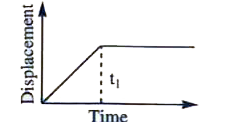 View Solution
The outpout Y of the logic circuit shown in figure is best represented as
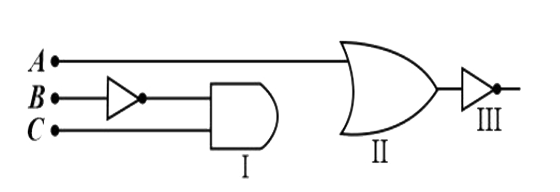 View Solution
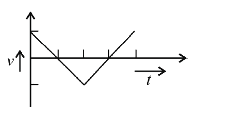
The graph in figure shows the velocity v versus time t for a body. Which of the graphs shown in figure represents the correesponding acceleration versus time graphs ?
 View Solution
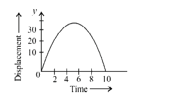
The displacement-time graph of a moving object is shown in figure. Which of the velocity-time graphs shown in figure could represent the motion of the same body ?
 View Solution
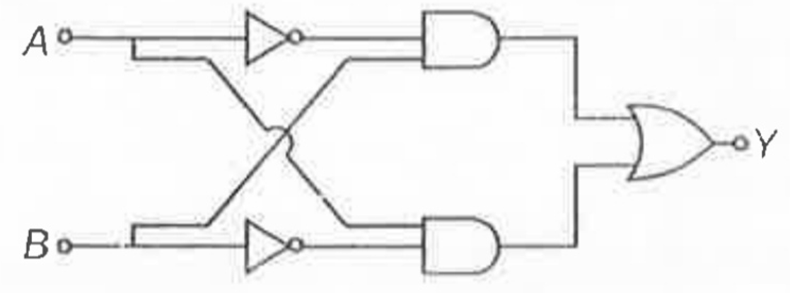
The logic circuit (figure) represents which logic gate?
 View Solution
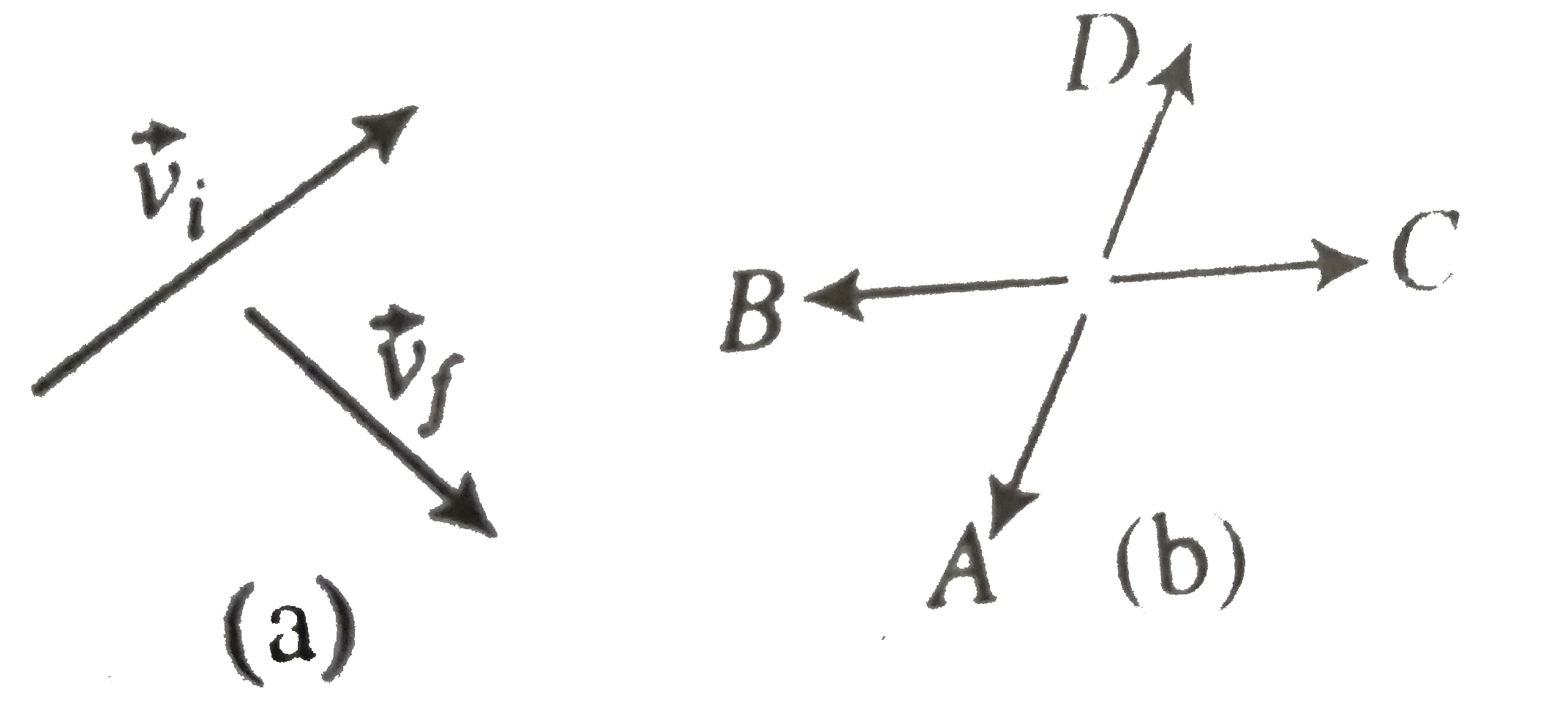
The initial and final velocities of an object are as shown in figure(a). Which arrows shown in figure(b) can be represent average acceleration vector?
 View Solution
The output (X) of the logic circuit shown in figure will be
 View Solution


