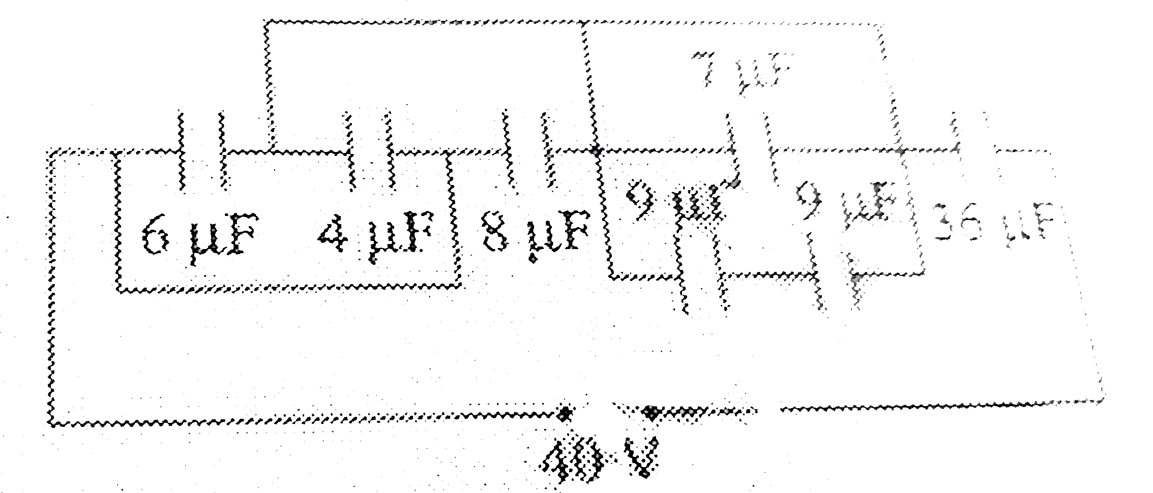
In the following diagram, the charge and potential difference across 8μF capacitance will be respectively

A
320μC,40V
B
420μC,50V
C
214μC,27V
D
360μC,45V
Video Solution
Text Solution
The correct Answer is:C

V8=3654×40=803 Volt ≈ 27 Volt
Q=803×8=6403=213.3μ≈214μC
|
Topper's Solved these Questions
- ELECTROSTATICSBOOK - ERRORLESSCHAPTER - ELECTROSTATICSEXERCISE - PAST YEARS QUESTIONS
56 Videos
- ELECTROSTATICSBOOK - ERRORLESSCHAPTER - ELECTROSTATICSEXERCISE - ASSERTION & REASON
25 Videos
- ELECTROSTATICSBOOK - ERRORLESSCHAPTER - ELECTROSTATICSEXERCISE - NCERT BASED QUESTIONS (Capacitance)
59 Videos
- ELECTRONICSBOOK - ERRORLESSCHAPTER - ELECTRONICSEXERCISE - Assertion & Reason
26 Videos
- MAGNETIC EFFECTS OF CURRENT BOOK - ERRORLESSCHAPTER - MAGNETIC EFFECTS OF CURRENT EXERCISE - ASSERTION & REASON
18 Videos
Similar Questions
Knowledge Check
In the follwong diagram the charge and potential difference across 8μF. Will capacitance will be respectively
 A320μC,40VB420μC,50VC214μC,27VD360μC,45V
Two condensers of capacities 8μF,and4μF are connected in parallel across a potential difference of 120 V. The charge and potential difference across 4μF capacitior is respectively
A1 mC, 10 VB0.2 mC, 20 VC0.4 mC, 60 VD0.48 mC, 120 VIn the adjoning figure, the potential difference across the 4.5μF capacitor is
 A4 VB6 VC8 VD4.5 V
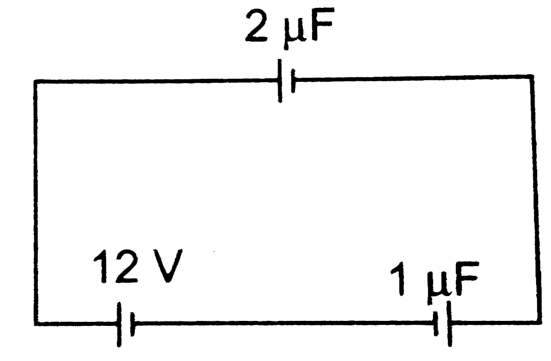
In a ircuit shown in figure, the potential difference across the capacitor of 2μF is
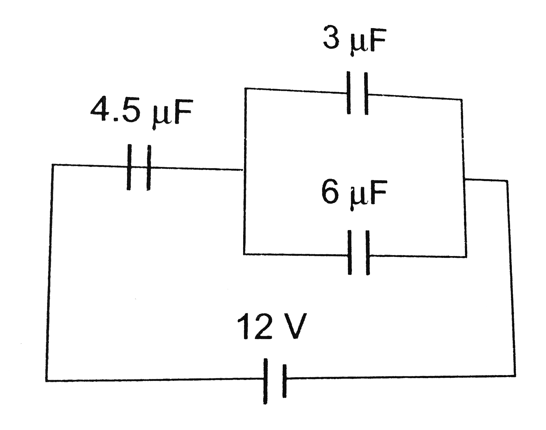
View SolutionIn the circuit shown in the figure, the potential difference across the 4.5μF capacitor is
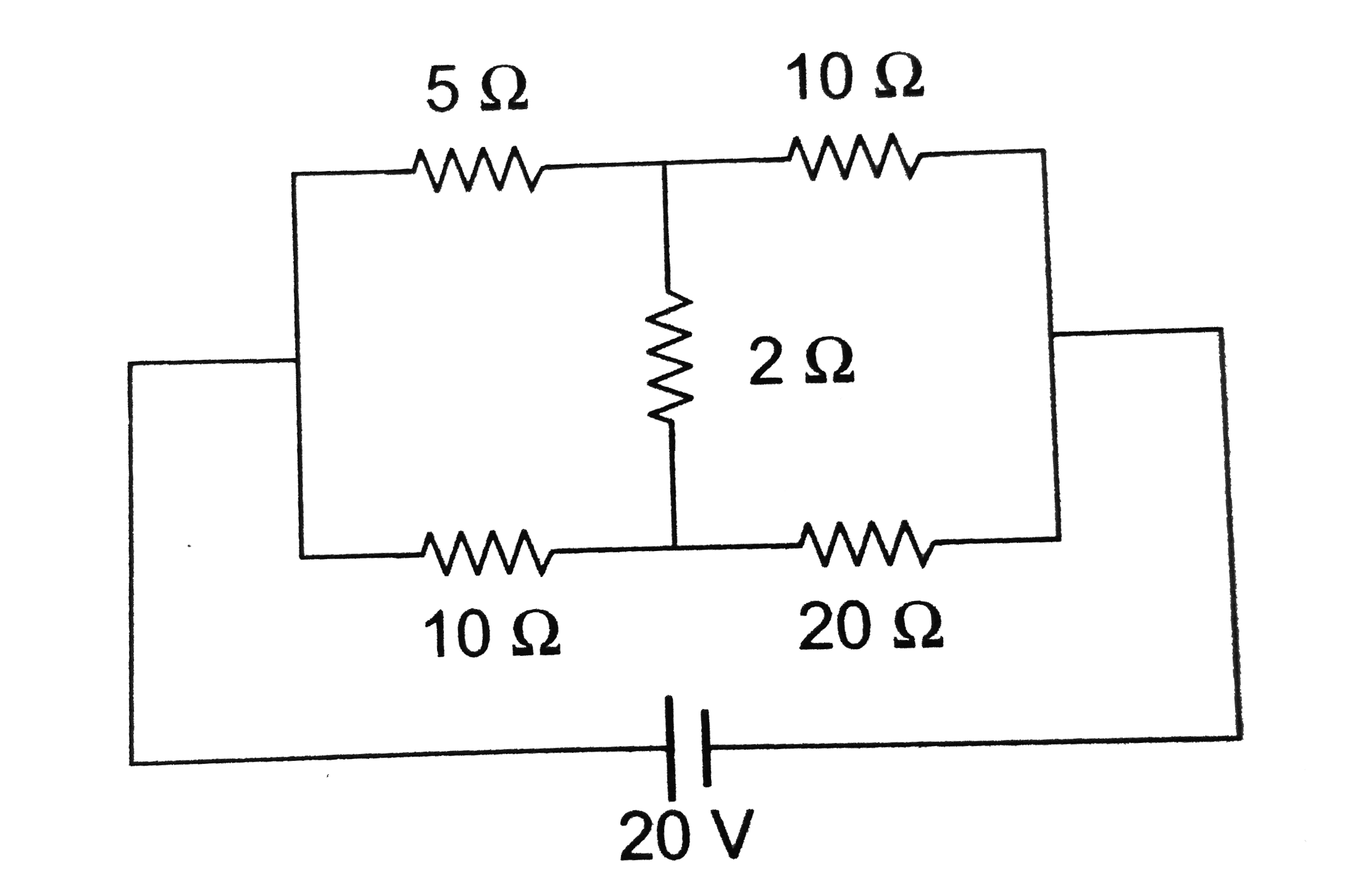
View SolutionIn the given circuit diagram, potential difference across 2Ω resistance is
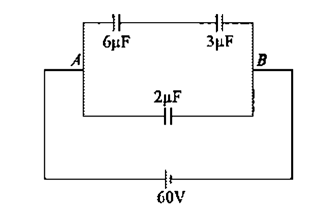
View SolutionIn the circuit shown, the potential difference across the 3μF capacitor is V and the equivalent capacitance between A and B is C Then:
View SolutionTwo capacitors of capacitances 10μFand20μF are connected in series across a potential difference of 100V. The potential difference across each capacitor is respectively
View Solution

