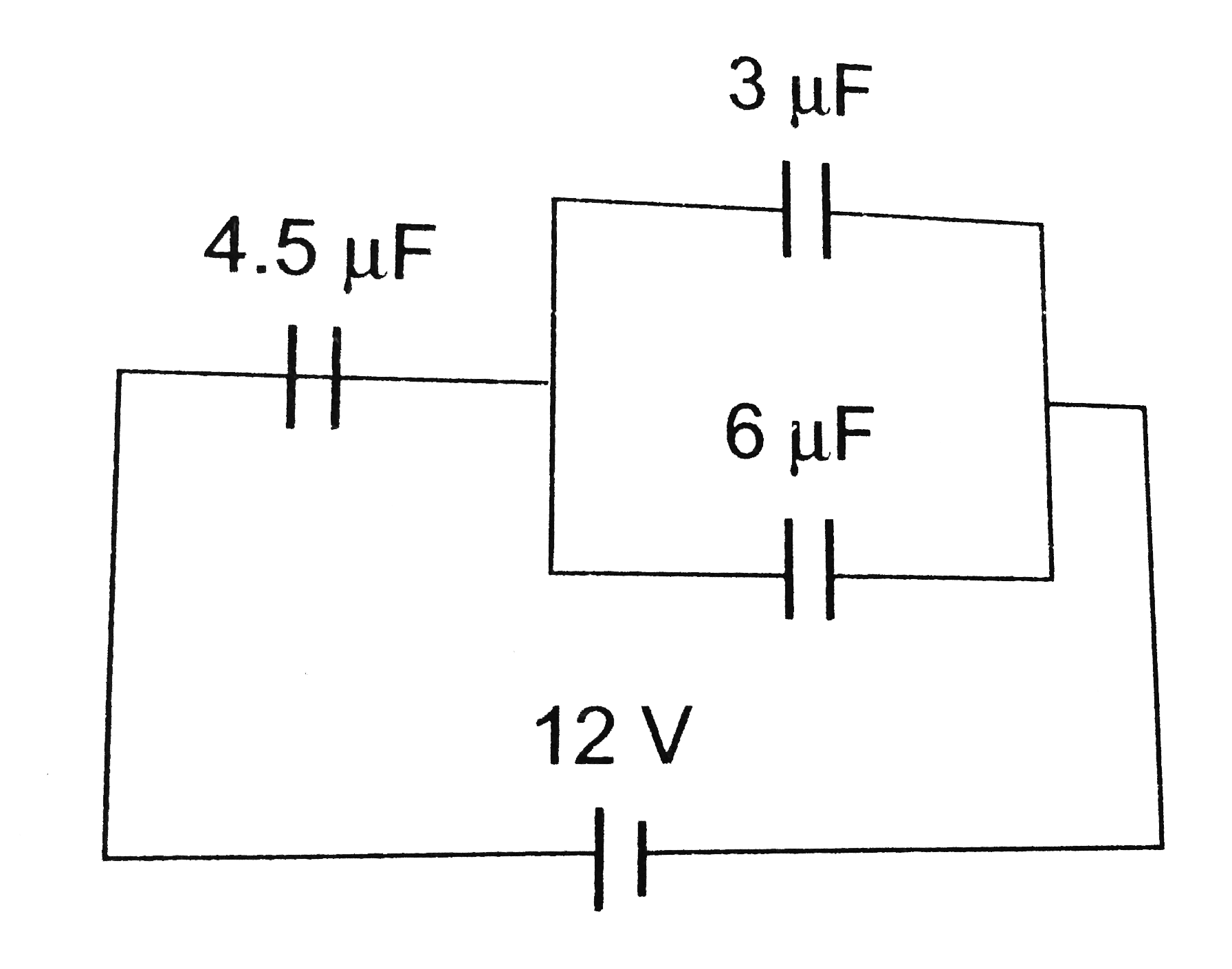
In the circuit shown in the figure, the potential difference across the 4.5μF capacitor is
83 volts
4 volts
6 volts
8 volts
The correct Answer is:D
4.5mF=92μF

V4.5=(94.5+9)×12=8 Volt.
Topper's Solved these Questions
- ELECTROSTATICSBook:ERRORLESSChapter:ELECTROSTATICSExercise:ASSERTION & REASON
Explore 25 Videos
- ELECTROSTATICSBook:ERRORLESSChapter:ELECTROSTATICSExercise:NCERT BASED QUESTIONS (Grouping of Capacitors)
Explore 58 Videos
- ELECTRONICSBook:ERRORLESSChapter:ELECTRONICSExercise:Assertion & Reason
Explore 26 Videos
- MAGNETIC EFFECTS OF CURRENT Book:ERRORLESSChapter:MAGNETIC EFFECTS OF CURRENT Exercise:ASSERTION & REASON
Explore 18 Videos
Similar Questions
Knowledge Check
In the adjoning figure, the potential difference across the 4.5μF capacitor is
 A4 VB6 VC8 VD4.5 V
In the circuit shown in the figure, the potential difference across the 4.5μF capacitor is
 A8/3 voltB4 voltC6voltD8volt
In the circuit shown, the potential difference across the 3μF capacitor is V and the equivalent capacitance between A and B is C Then:
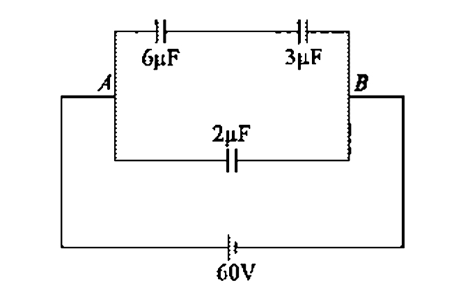 AC=4μFBC=11μFCV=20VDV=40V
In a ircuit shown in figure, the potential difference across the capacitor of 2μF is
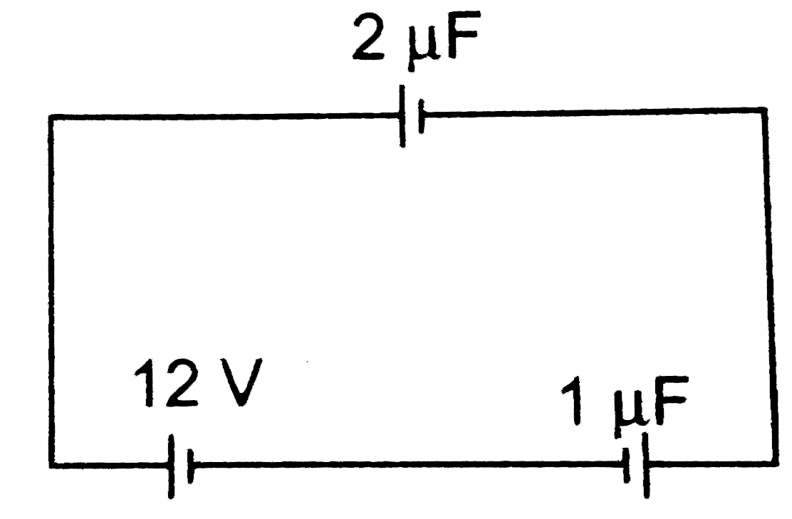
View SolutionIn the circuit shown in figure
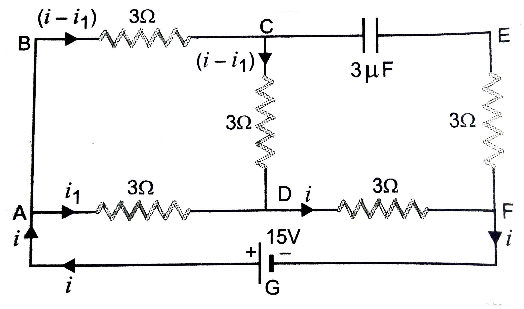
Find the potential differnece across capacitor.
View SolutionIn the circuit shown in the Figure, find the ratio of potential difference across capacitor 1 and 2. The capacitance values are as indicated in the Figure.
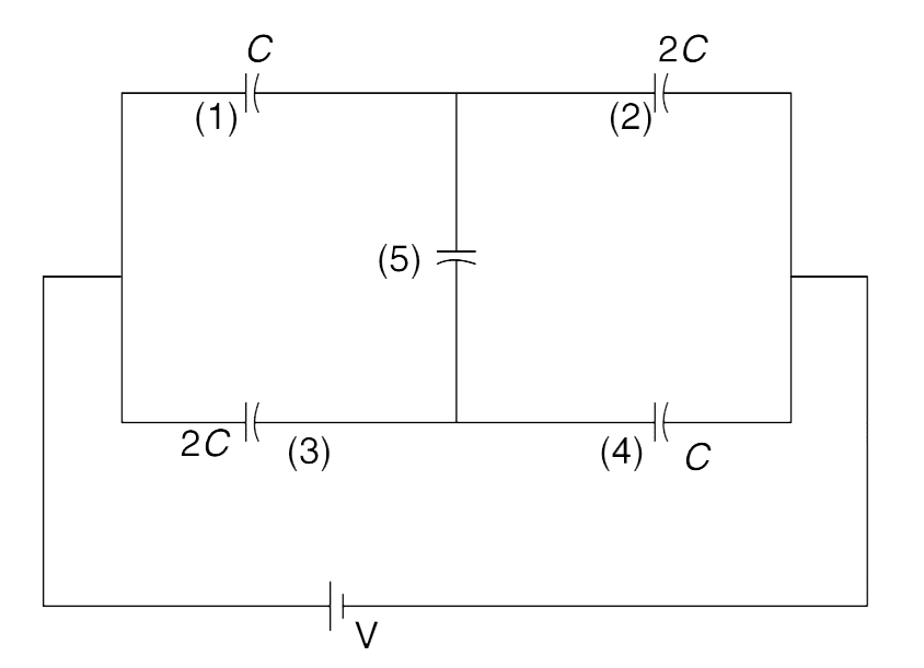
View SolutionTwo capacitor of capacitance 2μFand3μF respectively are charged to potential difference 20 V each. Now the capacitors are connected such that the positively chargd plate of one capacitory is connected to the negatively charged plate of the other. after the current in the circuit has become negligible, the potential difference across the 2μF capacitor is ____V.
View SolutionIn the given circuit, with steady current, the potential difference across the capacitor is
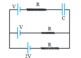
View Solution

