In the circuit shown below, an input of 1V is fed into the inverting input of an ideal OP- amplifier. The output signal Vout will be

A
+10V
B
−10V
C
0V
D
Infinity
Video Solution
Text Solution
The correct Answer is:B
V0=−(10×1031×103)×1=−(RfRi)Vi⇒V0=−10V
|
Updated on:21/07/2023
Topper's Solved these Questions
- BOOK - ERRORLESSCHAPTER - ELECTRONICSEXERCISE - NCERT Based Questions (Digital Electronics)23videos
ELECTRONICS
- BOOK - ERRORLESSCHAPTER - ELECTRONICSEXERCISE - Past years questions73videos
ELECTRONICS
- BOOK - ERRORLESSCHAPTER - ELECTRONICSEXERCISE - NCERT Based Questions (Semiconductor Diode)49videos
ELECTRONICS
- BOOK - ERRORLESSCHAPTER - ELECTRON, PHOTON, PHOTOELECTRIC EFFECT & X -RAYEXERCISE - ASSERTION & REASON27videos
ELECTRON, PHOTON, PHOTOELECTRIC EFFECT & X -RAY
- BOOK - ERRORLESSCHAPTER - ELECTROSTATICSEXERCISE - ASSERTION & REASON25videos
ELECTROSTATICS
Similar Questions
Knowledge Check
- Question 1 - Select One
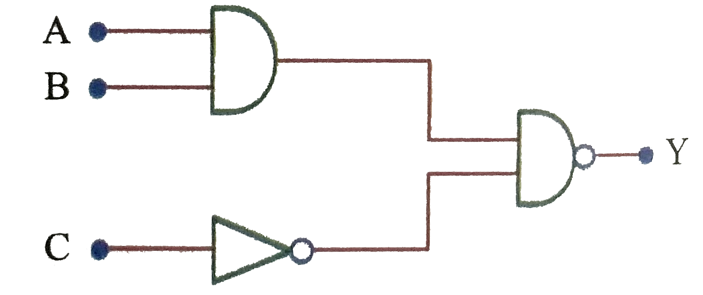
In the circuit Fig. the output y becomes zero for the inputs
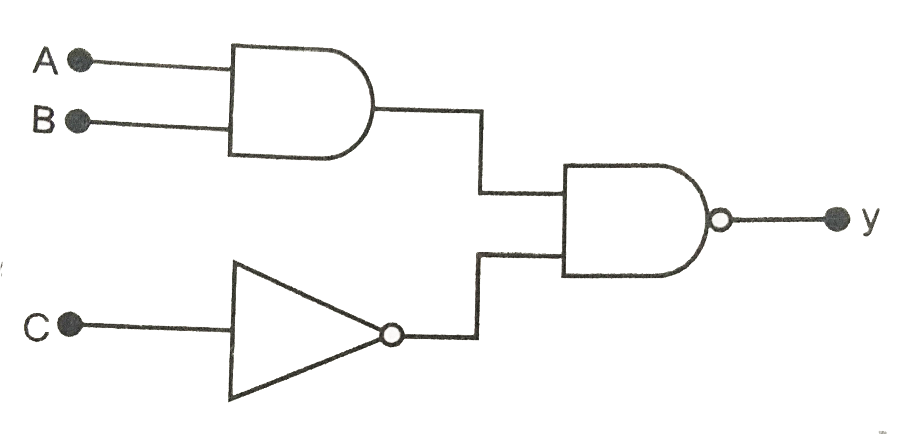 AA=1,B=0,C=0BA=0,B=1,C=1CA=0,B=0,C=0DA=1,B=1,C=0
 - Question 2 - Select One
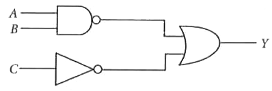
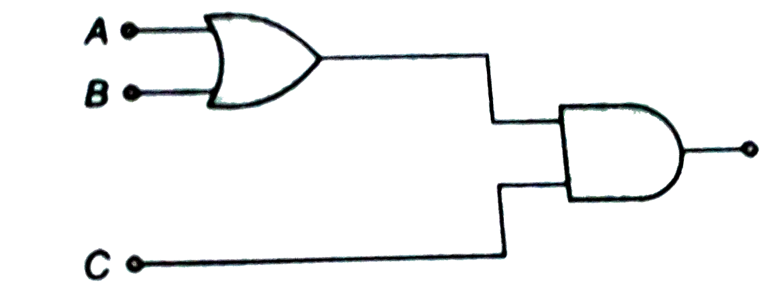
To get an output y=1 from the circuit shown below, the input must be
 AABC010BABC001CABC101DABC100
 - Question 3 - Select One
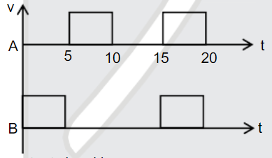
The inputs to the digital circuit are shown below. The output Y is
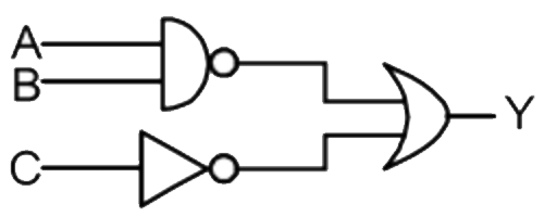 AA+B+¯¯¯CB(A+B)¯¯¯CC¯¯¯A+¯¯¯B+¯¯¯CD¯¯¯A+¯¯¯B+C
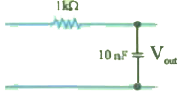
If an input of 50mV is applied as Vin then Vout at 100kHz will be
 View Solution
To get an output 1 from the circuit shown in the figure, the input must be
 View Solution
The output of a 2-input OR gate is fed to a NOT gate, the new gate obtained is
View SolutionIn the following circuit the output Y becomes zero for the inputs
 .View Solution
input are given as shown
then output signal is-View Solution


