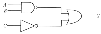
The inputs to the digital circuit are shown below. The output Y is

A+B+¯¯¯C
(A+B)¯¯¯C
¯¯¯A+¯¯¯B+¯¯¯C
¯¯¯A+¯¯¯B+C
Step by step video & image solution for The inputs to the digital circuit are shown below. The output Y is by Physics experts to help you in doubts & scoring excellent marks in Class 12 exams.
Updated on:21/07/2023Topper's Solved these Questions
- SOLID STATE ELECTRONS Book:MTG-WBJEEChapter:SOLID STATE ELECTRONS Exercise:WB JEE WORKOUT (CATEGORY 3 : One or More than one option Correct Type)
Explore 10 Videos
- PARTICLE NATURE OF LIGHT AND WAVE PARTICLE DUALISMBook:MTG-WBJEEChapter:PARTICLE NATURE OF LIGHT AND WAVE PARTICLE DUALISMExercise:WB JEE PREVIOUS YEARS QUESTIONS
Explore 15 Videos
- THERMODYNAMICSBook:MTG-WBJEEChapter:THERMODYNAMICSExercise:WB JEE Previous Years Questions
Explore 12 Videos
Similar Questions
Knowledge Check
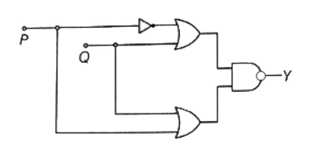
In the given circuit P and Q from the inputs. The output Y is
 AY=¯¯¯PBY=P¯¯¯QCY=P+QDY=¯¯¯Q
The output Y of the logic circuit as shown in figure is
 A(A+B)⋅¯¯¯CB(A+C)⋅¯¯¯CC(B+C)⋅¯¯¯ADA+B+C
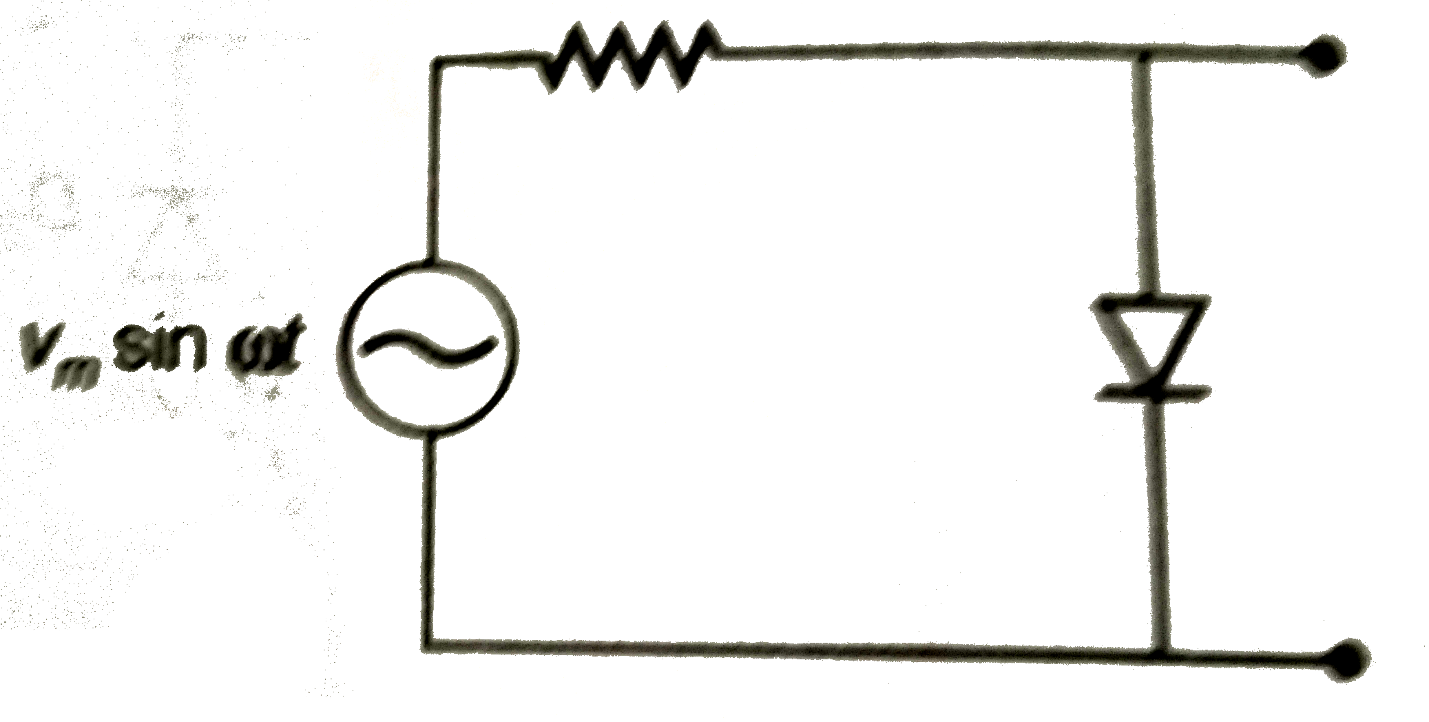
The output of the given circuit in figure given below,
 Awould be zero at all timesBwould be like a half wave rectifier with positive cycles in outputCwould be like a half wave rectifier with negative cycles in ouputDwould be like that of a full wave reactifier.
Draw the output waveformed at X, using the given inputs A and B for the logic circuit shows below. Also, identify the logic operation performed by this circuit.

View SolutionDraw the output waveform X, using the given inputs A and B for the logic circuit shows below. Also, identify the logic operation performed by this circuit.

View SolutionTo get an output y=1 from the circuit shown below, the input must be

View SolutionOutput of the circuit shown below will be

View SolutionThe output Y of the gate circuit shown in the figure below is

View Solution

