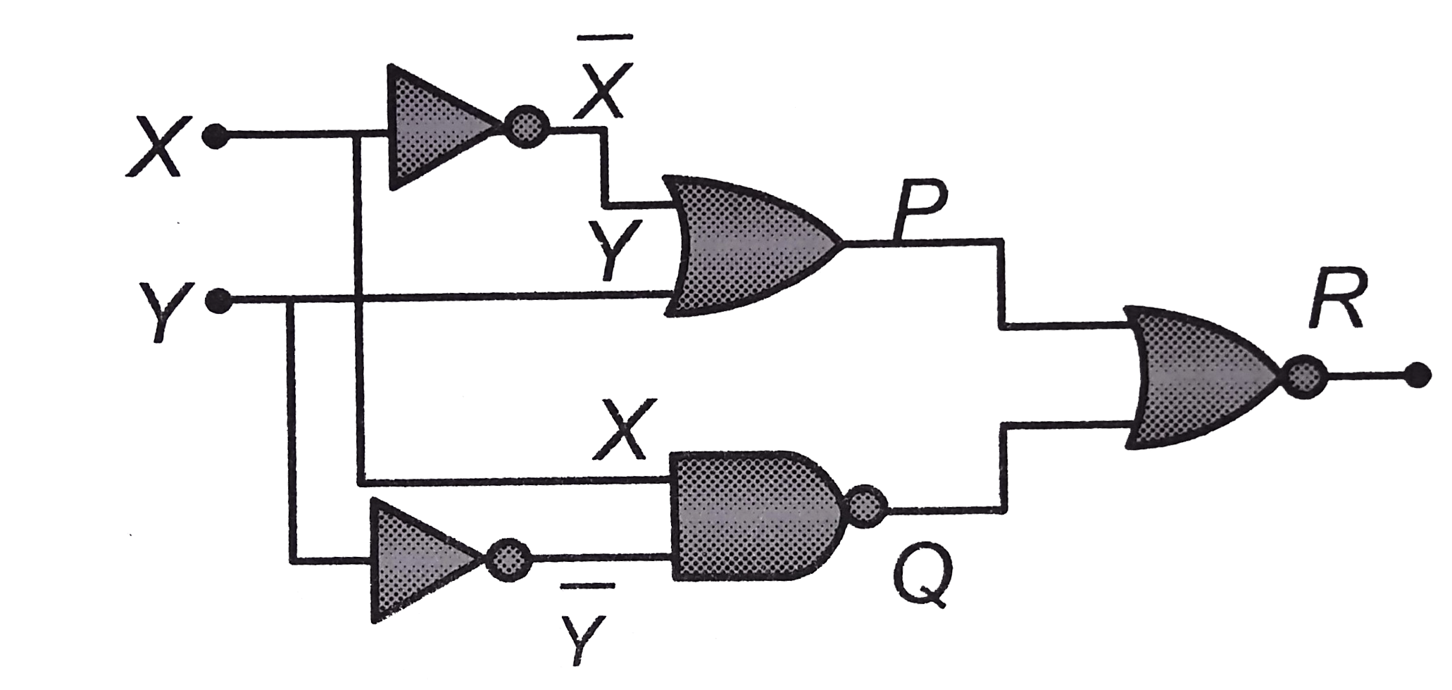
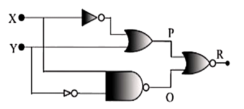
Figure gives a system of logic gates. From the study of truth table it can be found that no produce a high output (1) at R, we must have

A
X=0,Y=1
B
X=1,Y=1
C
X=1,Y=0
D
X=0,Y=0
Video Solution
Text Solution
The correct Answer is:C
|
Topper's Solved these Questions
- ELECTRONICSBOOK - ERRORLESSCHAPTER - ELECTRONICSEXERCISE - Past years questions
73 Videos
- ELECTRONICSBOOK - ERRORLESSCHAPTER - ELECTRONICSEXERCISE - Assertion & Reason
26 Videos
- ELECTRONICSBOOK - ERRORLESSCHAPTER - ELECTRONICSEXERCISE - NCERT Based Questions (Junction Transistor)
29 Videos
- ELECTRON, PHOTON, PHOTOELECTRIC EFFECT & X -RAYBOOK - ERRORLESSCHAPTER - ELECTRON, PHOTON, PHOTOELECTRIC EFFECT & X -RAYEXERCISE - ASSERTION & REASON
27 Videos
- ELECTROSTATICSBOOK - ERRORLESSCHAPTER - ELECTROSTATICSEXERCISE - ASSERTION & REASON
25 Videos
Similar Questions
Knowledge Check
Figure gives a system of logic gates. From the study of truth table it can be found that no produce a high output (1) at R, we must have
 AX=0,Y=1BX=1,Y=1CX=0,Y=0DX=1,Y=0
For which logic gate the following statement is true?
All low inputs produce a high output.AORBANDCNANDDNOTAn OR gate gives a logic 1 output
Aonly when all inputs are logical 1.Bonly when any two inputs are logical 1.Cwhen all inputs are logical 0.Dwhen any one input is logical 1.
Give logic symbol and truth table for a NOT gate.
View SolutionGive the logic symbol, Boolean expression and truth table of NAND gate.
View SolutionWhat is a logic gate name the logic gate obtained from the figure and write its truth table

View SolutionWhich logic gate produces LOW output when any of the inputs in HIGH
View SolutionWhich logic gate produces LOW output when any of the inputs in HIGH
View Solution


