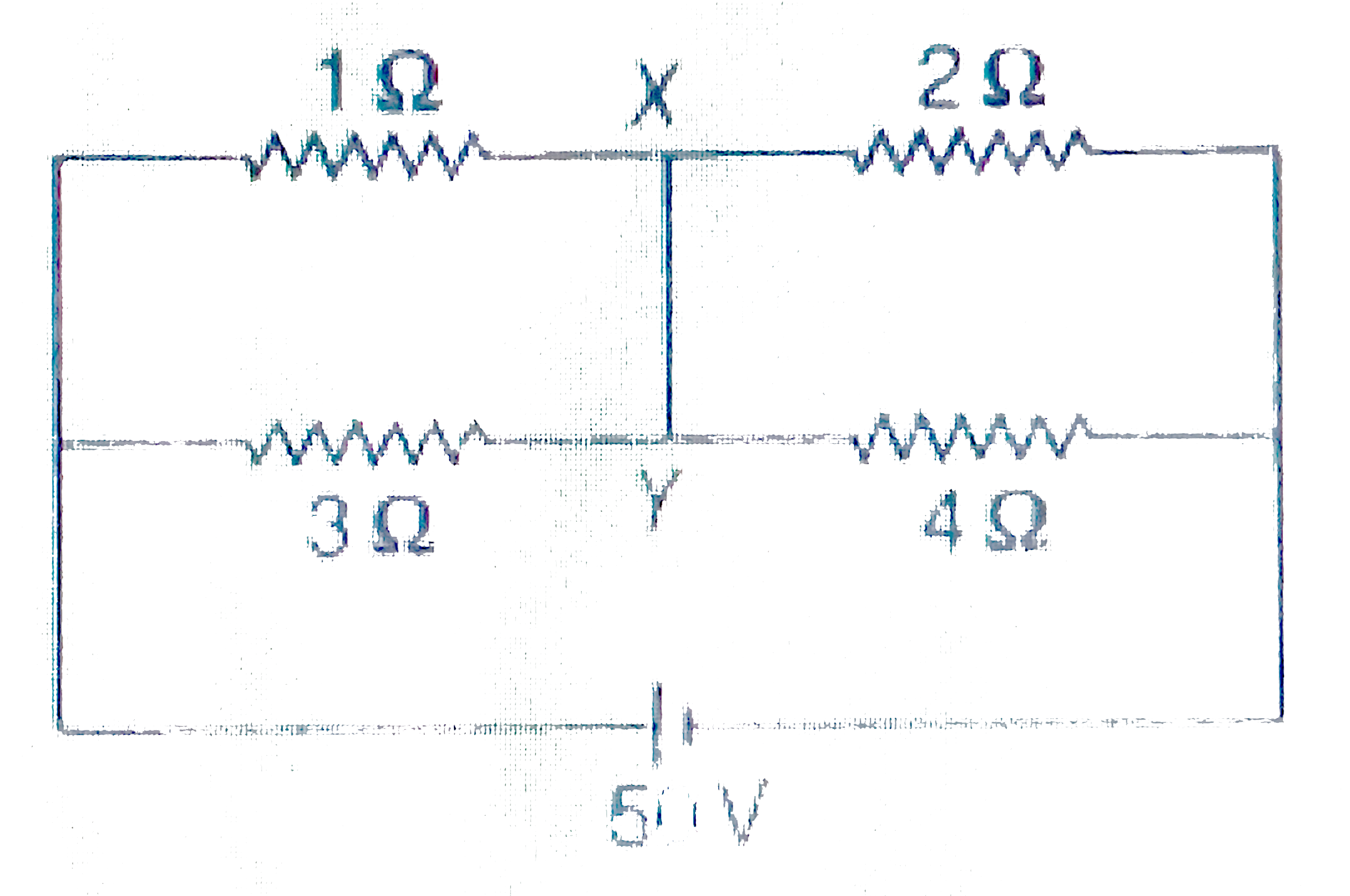
Current through wire XY of circuit shown is-

A
1A
B
4A
C
2A
D
3A
Video Solution
Text Solution
The correct Answer is:C
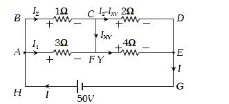
Loop ABCFA
−I2×1−0×IXY+3I1=0
⇒I2=3I1…….. (i)
Loop CDEFC
−2(I2−IXY)+4(I1+IXY)+0×IXY=0 …….. (ii)
⇒4I1−6I1+6IXY=0
Loop AFEGHA
−3I1−4(I1+IXY)+50=0
⇒−7I1−4IXY+50=0..... (iii)
From equation (ii)
⇒4I1−6I1+6IXY=0 ....... (iv)
Now, by elimination method
−14I1−8IXY+100=0→(iii)×2
−14I1+42IXY=0→(iv)×7
IXY=10050=2A
|
Topper's Solved these Questions
- CURRENT ELECTRICITYBOOK - ERRORLESSCHAPTER - CURRENT ELECTRICITYEXERCISE - NCERT BASED QUESTIONS (HEATING EFFECT OF CURRENT)
67 Videos
- CURRENT ELECTRICITYBOOK - ERRORLESSCHAPTER - CURRENT ELECTRICITYEXERCISE - PAST YEARS QUESTIONS
76 Videos
- CURRENT ELECTRICITYBOOK - ERRORLESSCHAPTER - CURRENT ELECTRICITYEXERCISE - NCERT BASED QUESTIONS (KIRCHHOFF.S LAW, CELLS)
53 Videos
- ATOMIC AND NUCLEAR PHYSICSBOOK - ERRORLESSCHAPTER - ATOMIC AND NUCLEAR PHYSICSEXERCISE - Assertion and Reason
23 Videos
- ELECTROMAGNETIC INDUCTIONBOOK - ERRORLESSCHAPTER - ELECTROMAGNETIC INDUCTIONEXERCISE - ASSERTION & REASON
20 Videos
Similar Questions
Knowledge Check
Current through XY of circuit shown is
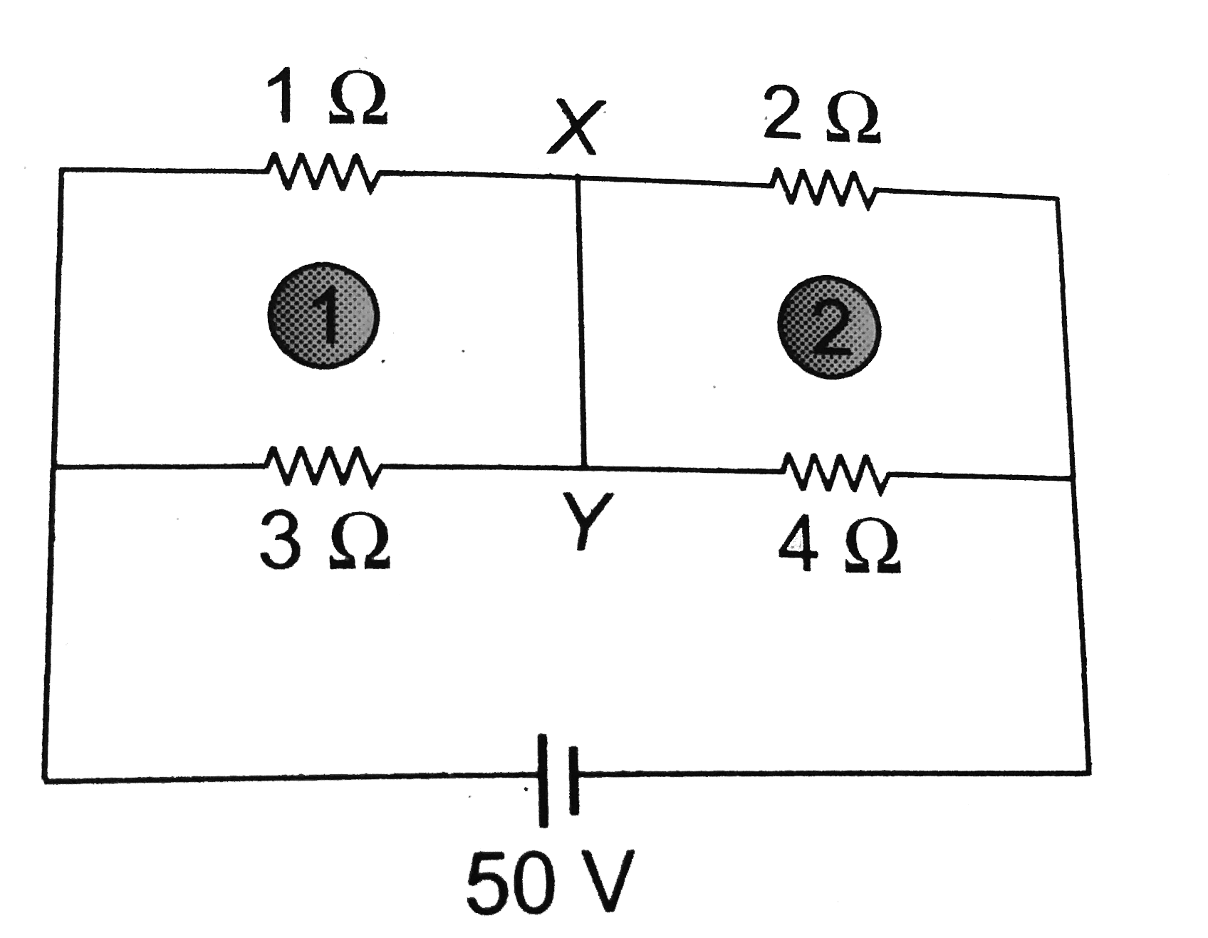 A1AB4AC2AD3A
Current through the battery in the circuit shown in the figure
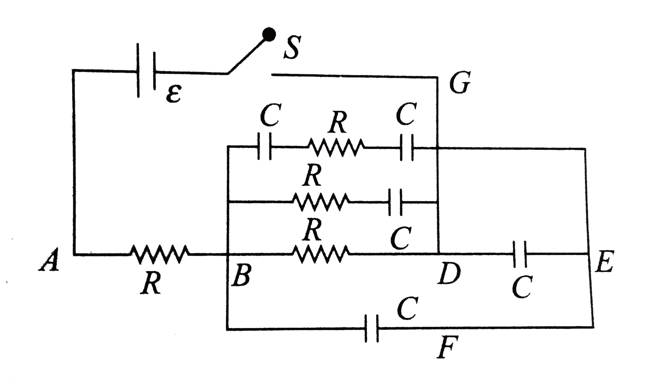 Aimmediately after the switch S is closed is ε/RBimmediately after the switch S is closed is ε/2R.Cafter long time is ε/2R.Dafter long time is 3ε/4R
Consider the circuit shown in the figure. Both the circuits are taking same current from battery but current through R in the second circuit is 110th of current through R in the first circuit. If R is 11Ω, the value of R1
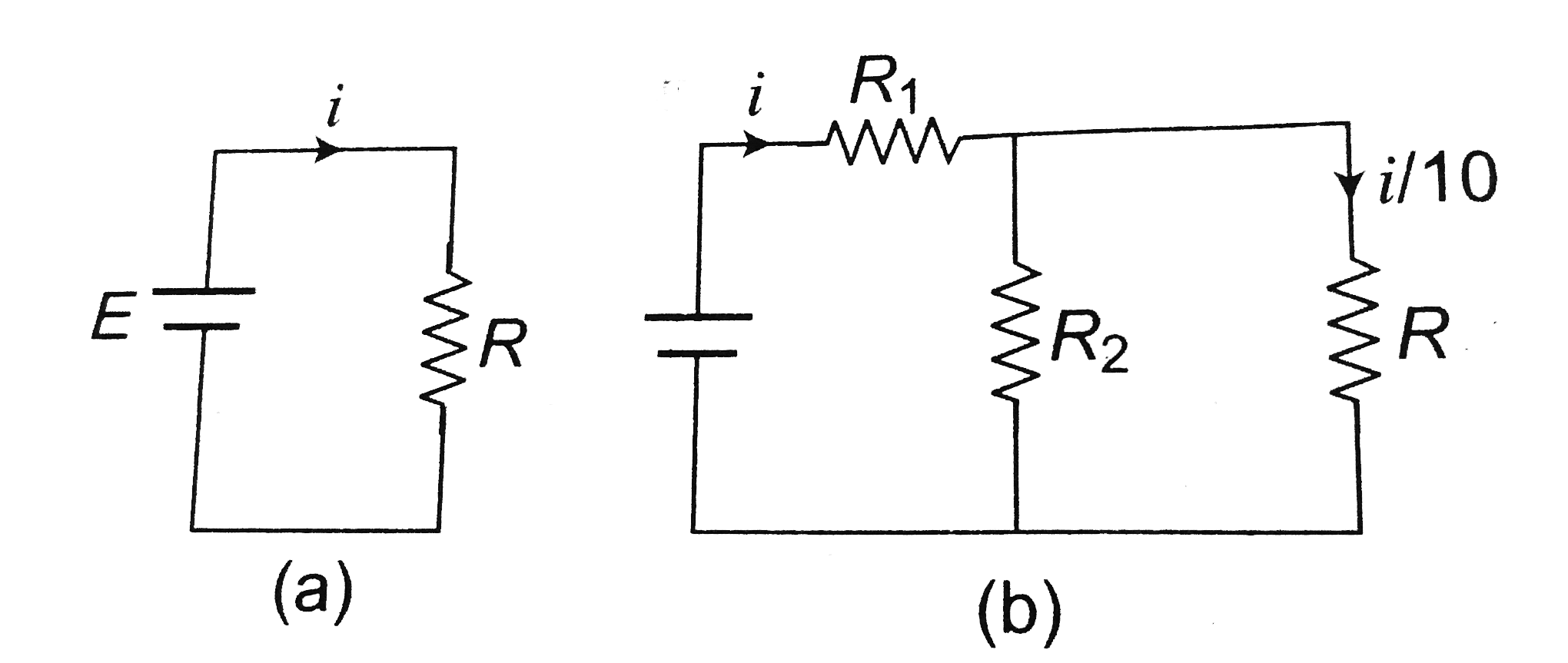 A9.9ΩB11ΩC8.8ΩD7.7Ω
The current flowing through the cell in the circuit shown is
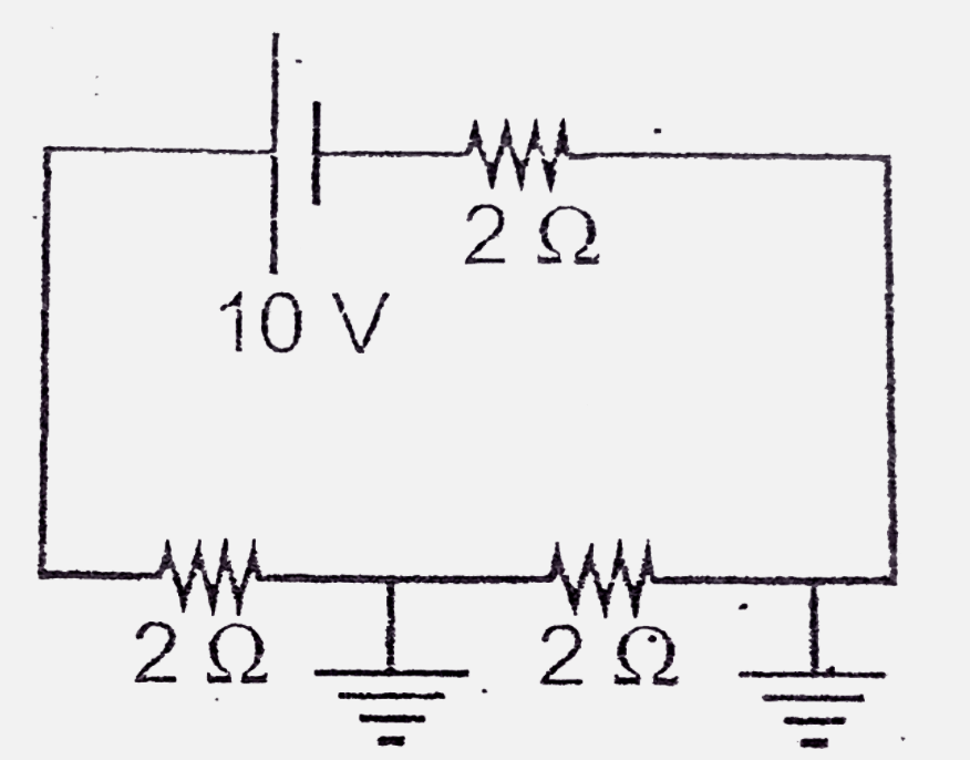
View Solution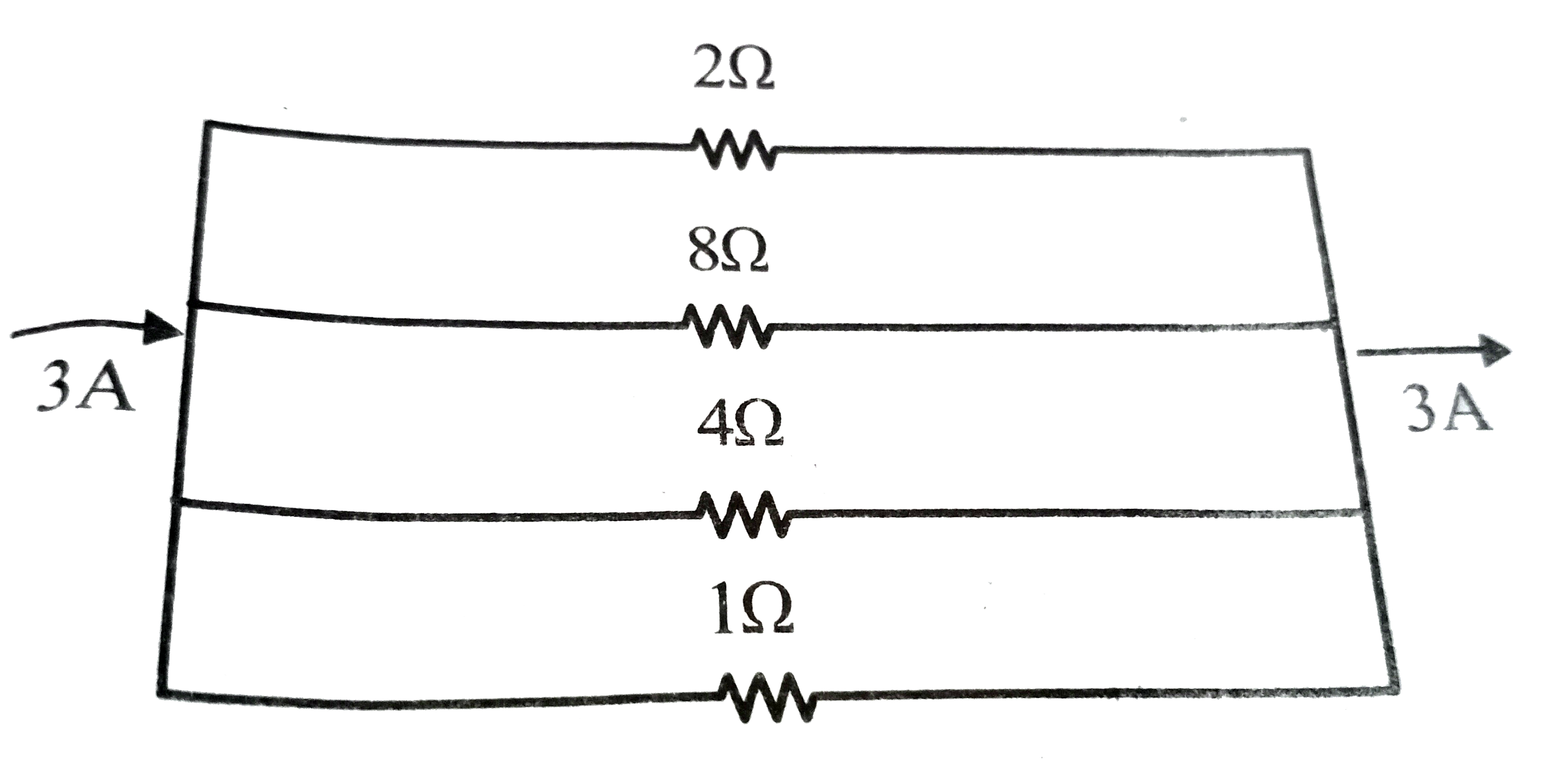
If an input current 3 A flows through the circuit shown above. What is the value of the current flowing through the 4Ω resistor ?
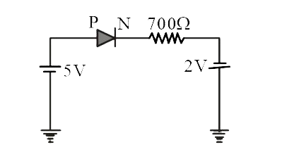
View SolutionThe current through an ideal PN junction shown in the following circuit diagram will be -
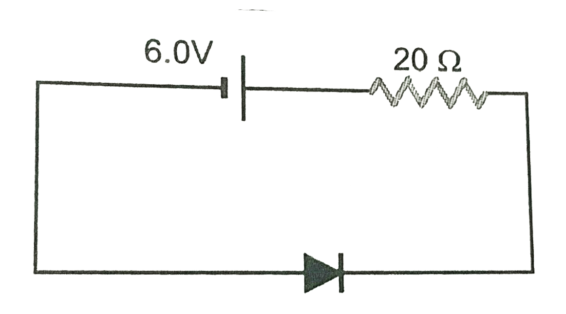
View SolutionCalculate the current through the circuit and the potential difference across the diode shown in Fig. The drift current for the diode is 30μA.
View SolutionThe current through an ideal PN junction shown in the following circuit diagram will be -

View Solution

