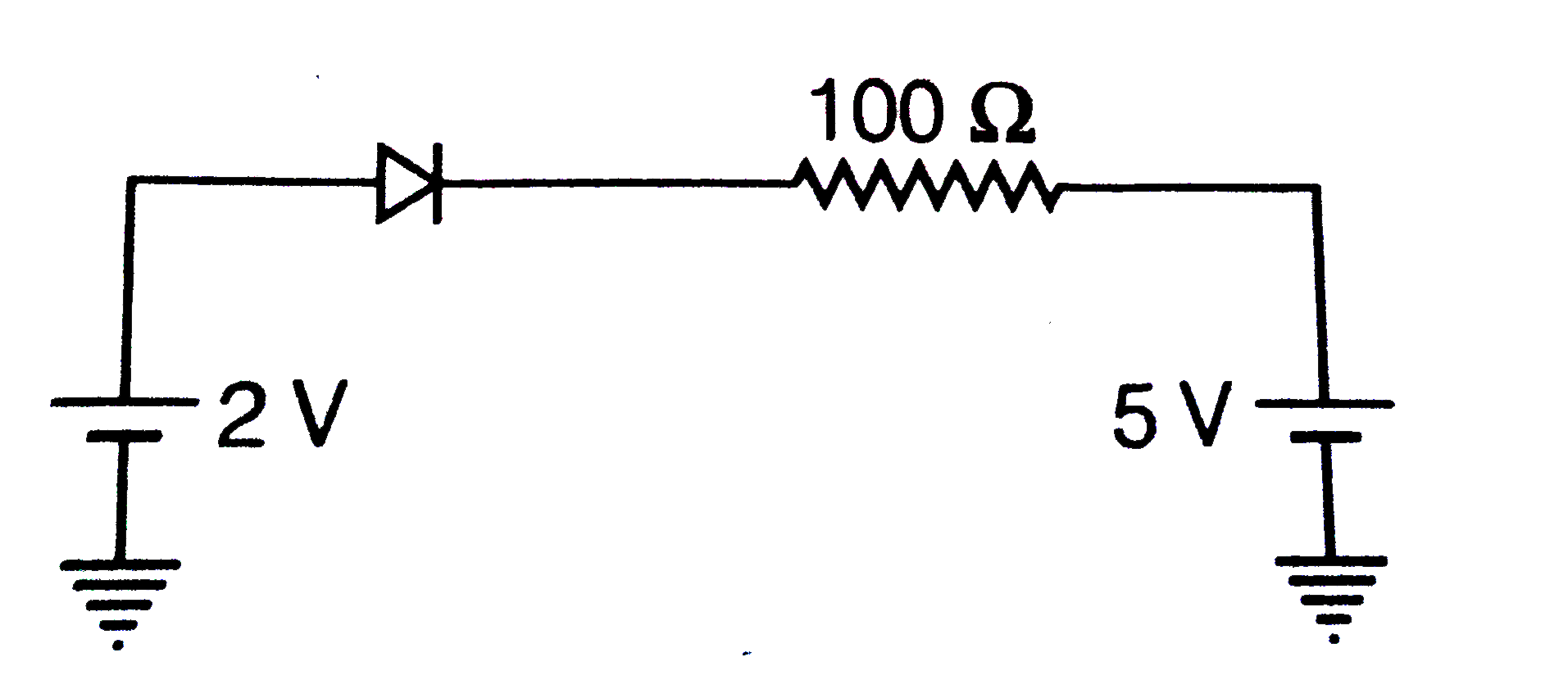
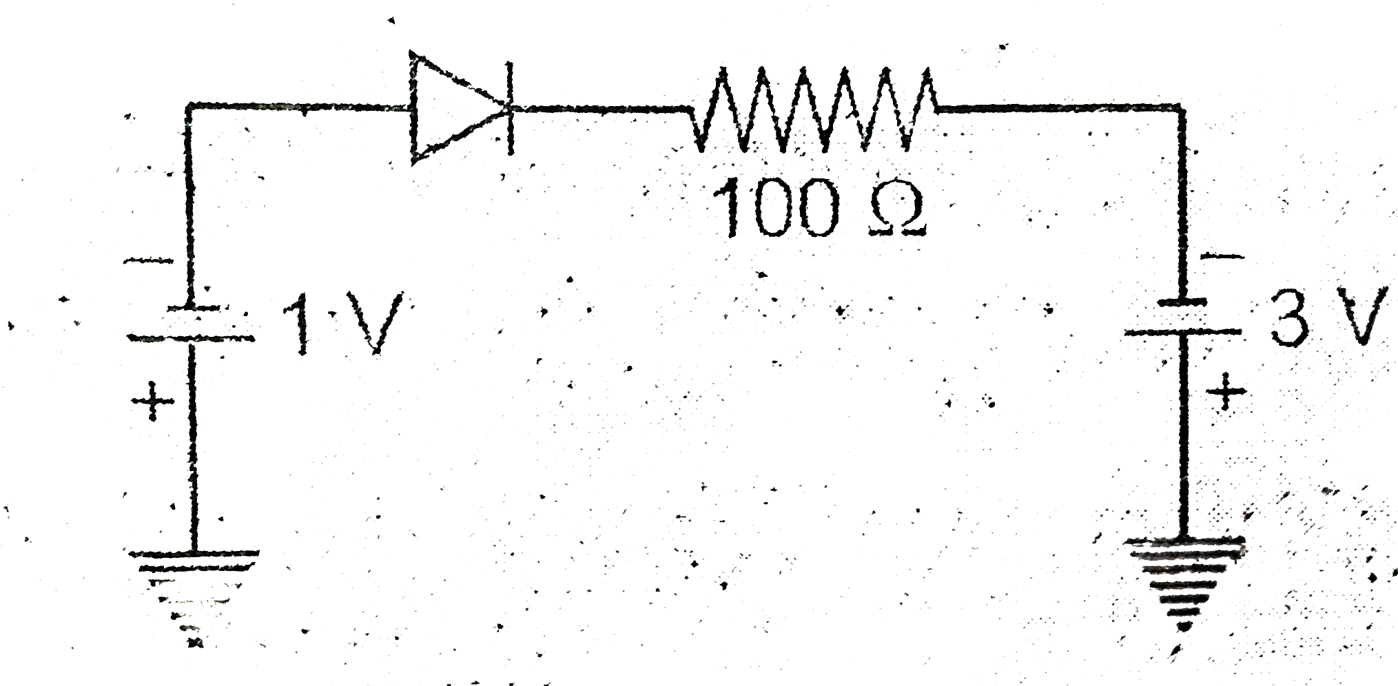
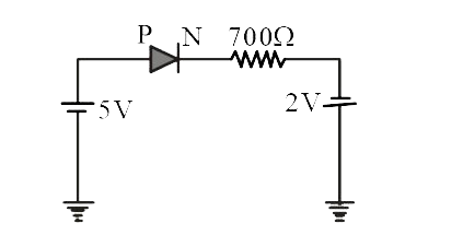
The current through an ideal PN junction shown in the following circuit diagram will be -
A
5mA
B
10mA
C
70mA
D
100mA
Video Solution
Text Solution
The correct Answer is:B
|
Answer
Step by step video & image solution for The current through an ideal PN junction shown in the following circuit diagram will be - by Physics experts to help you in doubts & scoring excellent marks in Class 12 exams.
Updated on:21/07/2023Topper's Solved these Questions
- SEMI CONDUCTOR AND LOGIC GATESBOOK - MOTIONCHAPTER - SEMI CONDUCTOR AND LOGIC GATESEXERCISE - EXERCISE 3
34 Videos
- SEMI CONDUCTOR AND LOGIC GATESBOOK - MOTIONCHAPTER - SEMI CONDUCTOR AND LOGIC GATESEXERCISE - EXERCISE 3
34 Videos
- ROTATIONAL MOTION BOOK - MOTIONCHAPTER - ROTATIONAL MOTION EXERCISE - Exercise - 3 ( Section-B )
24 Videos
- SIMPLE HARMONIC MOTIONBOOK - MOTIONCHAPTER - SIMPLE HARMONIC MOTIONEXERCISE - EXERCISE -3 Section - B Previous Year Problems | JEE MAIN
23 Videos
Similar Questions
Knowledge Check
The current through and ideal p-n junction shown in the following circuit diagram will be
 AzeroB1 mAC10 mAD30 mA
In a PN-junction
AHigh potential at N side and low potential at P sideBHigh potential P side and low potential at N sideCP and N both are at smae potentialDUndeterminedThe current through the ideal diode as shown in the is
 A0AB0.02AC0.04AD0.06A
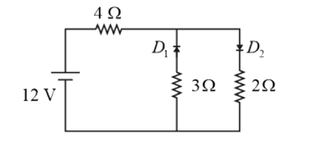
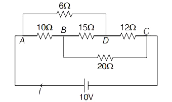
The current through the battery shown in the circuit is
View SolutionIn a PN-junction
View SolutionThe current through the ideal diode as shown in the figure is

View SolutionCurrent through the ideal diode as shown in figure is

View SolutionThe value of current I as shown in the given circuit diagram is
View Solution

