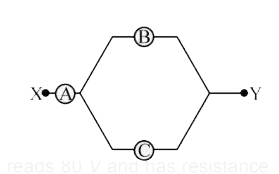
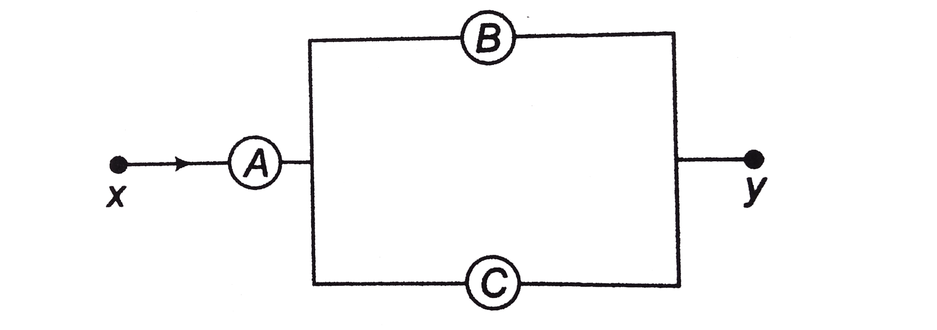
Three voltmeters A, B and C having resistances R, 1.5 R and 3 R respectively are used in a circuit as shown. When a potential difference is applied between X and Y, the readings of the voltmeters are V1,V2andV3respectively. Then :
V1=V2=V3
V1<V2=V3
V1>V2>V3
V1>V2=V3
The correct Answer is:A
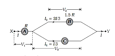
I1=(1.5R4.5R)I=l3
l2=(3R4.5R)×l=2I3
V1=IR,V2=V3=I.5R×23l=IR
Hence, V1=V2=V3
Topper's Solved these Questions
- BOOK - ERRORLESSCHAPTER - CURRENT ELECTRICITYEXERCISE - NCERT BASED QUESTIONS (HEATING EFFECT OF CURRENT)67videos
CURRENT ELECTRICITY
- BOOK - ERRORLESSCHAPTER - CURRENT ELECTRICITYEXERCISE - PAST YEARS QUESTIONS76videos
CURRENT ELECTRICITY
- BOOK - ERRORLESSCHAPTER - CURRENT ELECTRICITYEXERCISE - NCERT BASED QUESTIONS (KIRCHHOFF.S LAW, CELLS)53videos
CURRENT ELECTRICITY
- BOOK - ERRORLESSCHAPTER - ATOMIC AND NUCLEAR PHYSICSEXERCISE - Assertion and Reason23videos
ATOMIC AND NUCLEAR PHYSICS
- BOOK - ERRORLESSCHAPTER - ELECTROMAGNETIC INDUCTIONEXERCISE - ASSERTION & REASON20videos
ELECTROMAGNETIC INDUCTION
Similar Questions
Knowledge Check
- Question 1 - Select One
Three voltmeters A, B and C having resistances R, 1.5 R and 3 R respectively are used in a circuit as shown. When a potential difference is applied between X and Y, the readings of the voltmeters are V1,V2andV3respectively. Then :
 AV1=V2=V3BV1<V2=V3CV1>V2>V3DV1>V2=V3
 - Question 2 - Select One
A,B and C are voltmeters of resistance R, 1.5 R and 3R respectively as shown in the figure. When some potential difference is applied between X and Y, the voltmeter reading are VA,VBandVC respectively.
AVA=AB≠VCBVA≠VB≠VCCVA=AB=VCDVA≠VB=VC - Question 3 - Select One
A,B and C are voltmeters of resistances R,1.5R and 3R respectively. When some potential difference is applied between x and y the voltmeter readings are VA,V_BandV_C, then
 AVA=VB=VCBVA≠VB=VCCVA=VB≡VCDVA+VB=VC
Consider the circuit shown in the figure, the cell is ideal. The readings of the ideal voltmeters V1 and V2 in volts are respectively.
 View Solution
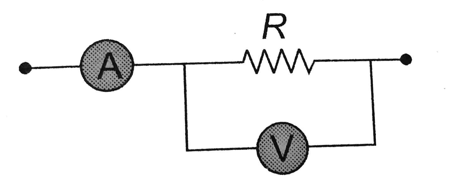
In the circuit shown the reading of ammeter and voltmeter are 4A and 20V respectively. The meters are non ideal, then R ia
 View Solution
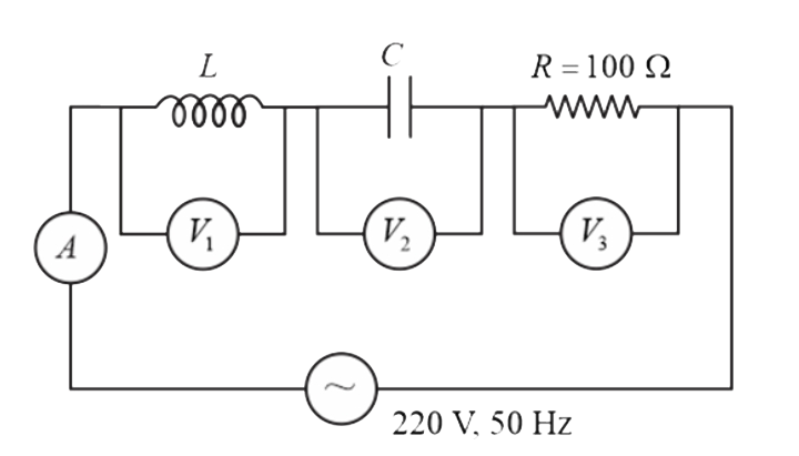
In the given circuit the reading of voltmeters V1andV2 are 300 volt each . The reading of the voltmeter V3 and ammeter A are respectively
 View Solution
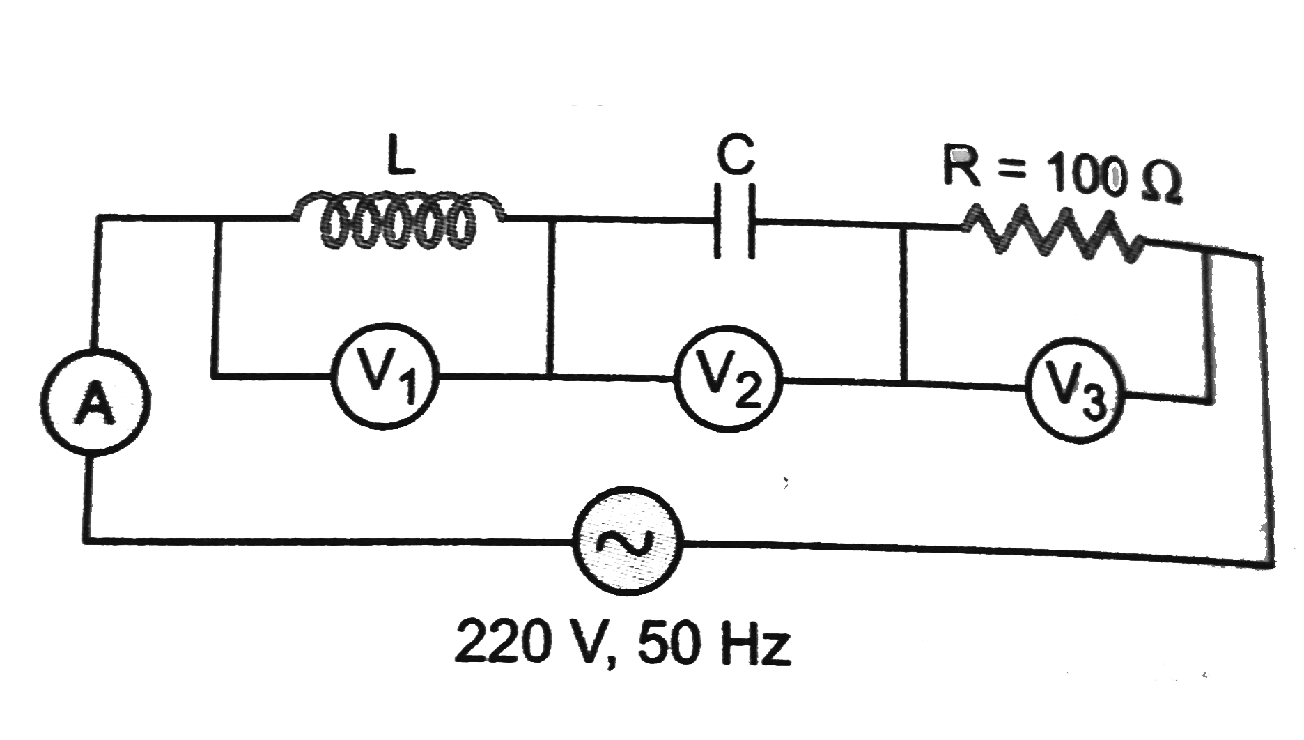
In the given circuit, Fig., the reading of voltmeter V1 and V2 300 votls each. The reading of the voltemeter V3 and ammeter A are respectively
 View Solution
In the circuit shown, A and V are ideal ammeter and voltmeter respectively. Reading of the voltmeter will be
 View Solution


