In the circuit shown, reactance of each capacitor is 4R, and that of each inductor is R3 . If R=5Ω then find reading of ammeter (in amperes)
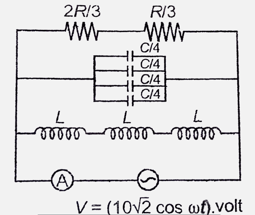
The correct Answer is:2
Step by step video & image solution for In the circuit shown, reactance of each capacitor is 4R, and that of each inductor is (R)/(3) . If R=5 Omega then find reading of ammeter (in amperes) by Physics experts to help you in doubts & scoring excellent marks in Class 12 exams.
Updated on:21/07/2023Topper's Solved these Questions
- ALTERNATING CURRENT BOOK - AAKASH INSTITUTECHAPTER - ALTERNATING CURRENT EXERCISE - Assignment (Section-H) (Multiple True-False Type Questions)
2 Videos
- ALTERNATING CURRENT BOOK - AAKASH INSTITUTECHAPTER - ALTERNATING CURRENT EXERCISE - Assignment (Section-I )(subjective Type Questions)
1 Videos
- ALTERNATING CURRENT BOOK - AAKASH INSTITUTECHAPTER - ALTERNATING CURRENT EXERCISE - Assignment (Section - F) (Matrix- Match Type Questions)
1 Videos
- ATOMSBOOK - AAKASH INSTITUTECHAPTER - ATOMSEXERCISE - ASSIGNMENT SECTION J (Aakash Challengers )
4 Videos
Similar Questions
Knowledge Check
In the circuit shown the resistance of voltmeter is 10000ohm and that of ammeter is 20ohm. The ammeter reading is 0.10amp and voltmeter reading is 12 volts. Then R is equal to
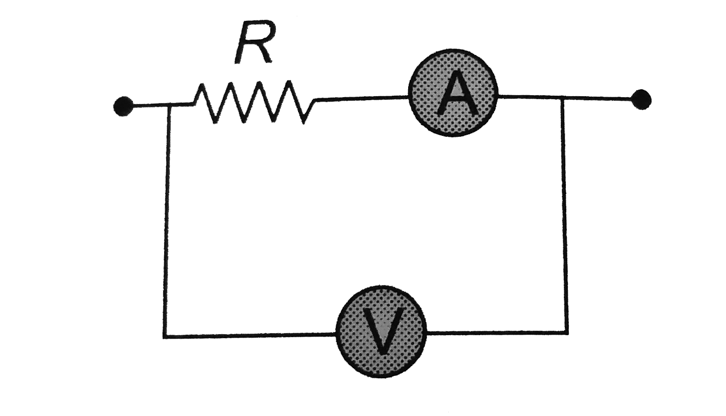 A122ΩB140ΩC116ΩD100Ω
In the circuit shwon in figure, ammeter and voltmeter are ideal. E=4V,R=15Ω and r=1Ω, then reading of ammter (in A) and voltmeter (in V) respectively are:
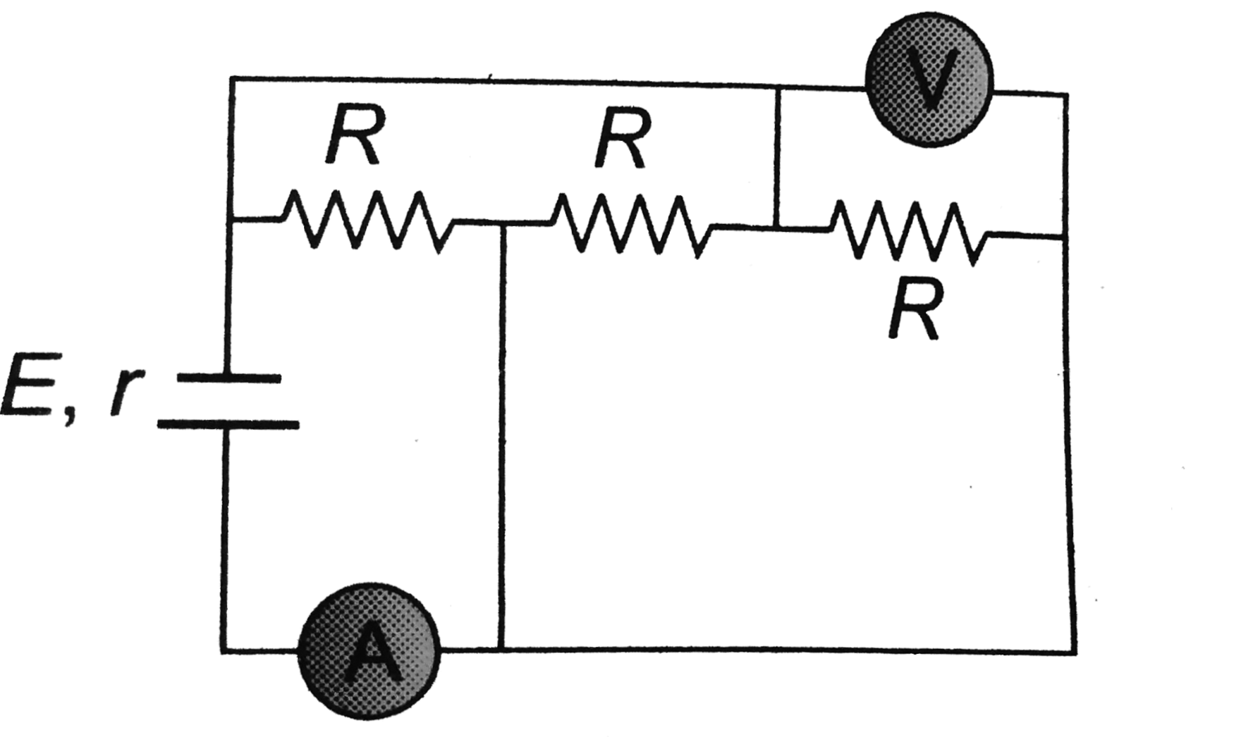 A2/3,11/3B2/3,10/3C10/3,2/3Dnone of these
In the circuit shown below, the ammeter reading is zero. Then, the value of the resistance R is
 A50ΩB100ΩC200ΩD400Ω
In a series LCR circuit the frequency of a 10V, AC voltage soure is adjusted in such a fashion that the reactance of the inductor meausers 15Ω and that of the capacitor 11Ω. If R=3Ω, the potentail difference across the series combination of L and Cwill be:
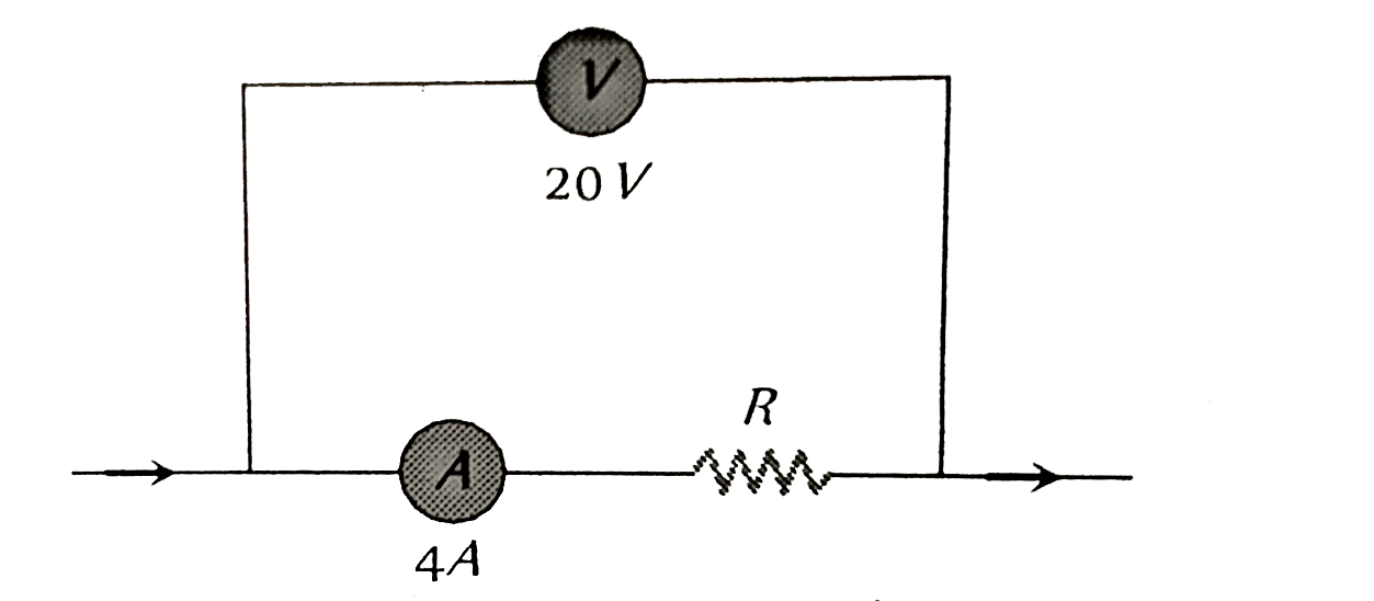
View SolutionIn the diagram shown, the reading of voltmeter is 20 V and that of ammeter is 4 A . The value of R should be (Consider given ammeter and voltmeter are not ideal)
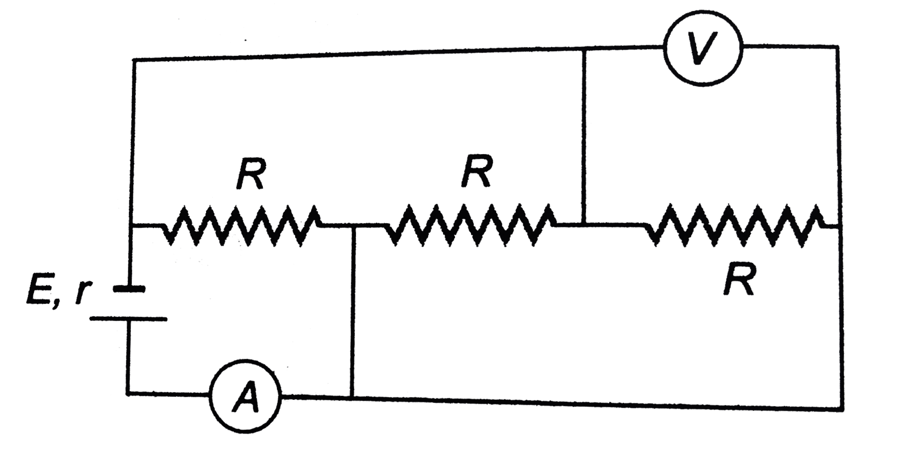
View SolutionIn the circuit shown in figure ammeter and voltmeter are ideal. If E=4V,R=9Ω and r=1Ω then readings of ammeter and voltmeter are
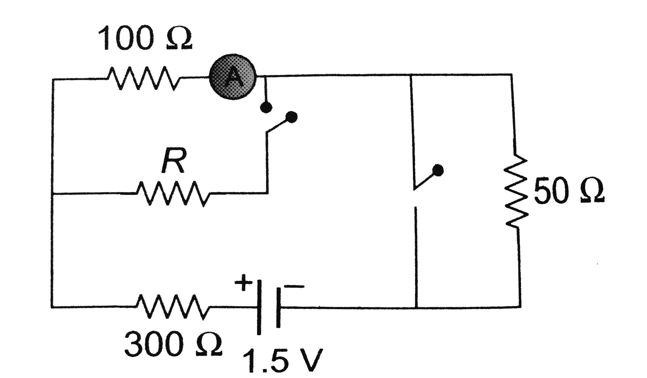
View SolutionIn the circuit shown in figure the reading of ammeter is the same with both switches open as with both closed. Then find the resistance R. (ammeter is ideal).
View SolutionIf resistance of voltmeter is 10000Ω and resistance of ammeter is 2Ω then find R when voltmeter reads 12 V and ammeter reads 0.1 A
View Solution

