A sinusoidally alternating emf is applied to an LCR series circuit . (i) Define the impedance of the circuit . (ii) Obtain the expressions for the impedance and the phase difference between the emf and current from the phasor diagram. (iii) Discuss the behaviour of the circuit for different relative values of the two reactances in the circuit.
Text Solution
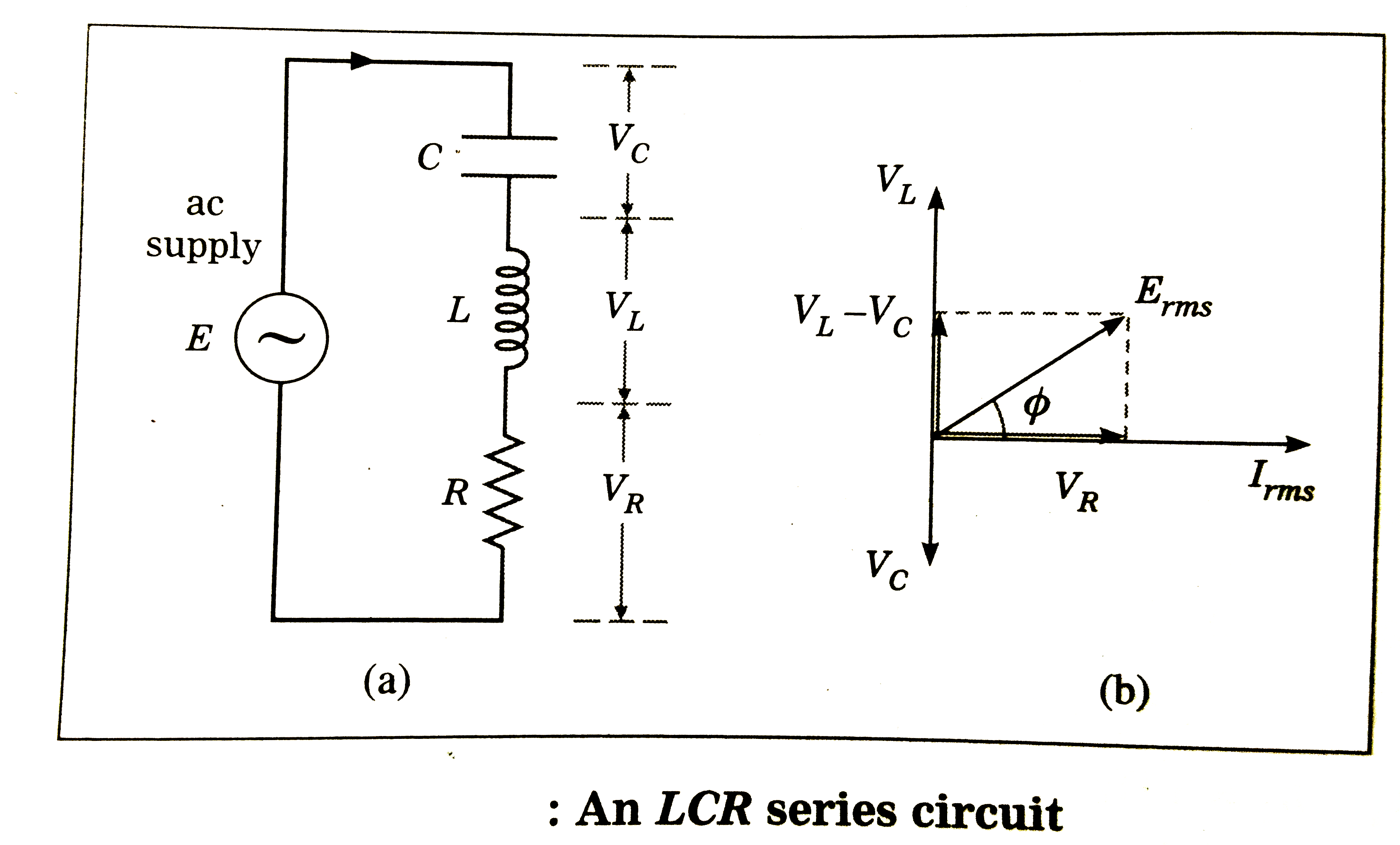
Suppose a sinusoidally alternating emf E, of peak value Eo and frequency f , is applied to a circuit containing a pure inductor ( inductance L), a resistor ( resistance R) and a capacitor (capacitance C), all in series, Fig (a).

(i) The impedance Z of the circuit is defined as the effective resistance offfered to an alternating current and is given by Z=Vrms/Irms .
(ii) Let the current at any instant be I=Iosinωt, where Io=Eo/Z≡ the peak current and ω=2πf.
The p.d. VR across the resistor is in phase with I and is given by VR=IR.
The p.d. VL acrose the inductor leads 90∘ on I, and VL(rms)=ωLIrms=XLIrms, where XL=ωL = the inductive reactance .
The p.d. VC across the capacitor lags 90∘ on I, and VC(rms)=IrmsωC=XCIrms,where XC=1/ωC = the capacitive reactance.
Since the current is the same for all the circuit elements, this is the first phasor drawn in the phasor diagram, Fig. (b) . Other phasors representing the instantaneous values of the sinusoidally alternating quantities are then drawn in relation to this.
In can be seen in the phasor diagram, that the p.d.s VLandVC are in antiphase so that the magnitude Erms of the vector sum of all three p.d.s is
Erms=√V2R+(VL−VC)2
=Irms√R2+(XL−CC)2
Hence, the impedance of the circuit is
Z=√R2+(XL−XC)2
=√R2+(ωL−1ωC)2
The phase difference ϕ between the emf and current is given by
tanϕ=VL−VCVR=XL−XCR=ωL−(1/ωC)R
(iii) If XL>XC,the circuit behaves inductively and the current legs on p.d. For XL<XC, the circuit behaves capacitively and the current leads on p.d. (ϕ negative). For XL=XC,ϕ=0, the current and emf are in phase, and the circuit is purely resistive.
|
Topper's Solved these Questions
- MODEL QUESTION PAPER BOOK - NAVNEET PUBLICATION - MAHARASHTRA BOARDCHAPTER - MODEL QUESTION PAPER EXERCISE - SECTION- C
12 Videos
- LAWS AND THEORIESBOOK - NAVNEET PUBLICATION - MAHARASHTRA BOARDCHAPTER - LAWS AND THEORIESEXERCISE - Assignments
2 Videos
- MODEL QUESTION PAPER FOR PRACTICEBOOK - NAVNEET PUBLICATION - MAHARASHTRA BOARDCHAPTER - MODEL QUESTION PAPER FOR PRACTICEEXERCISE - SECTION-D
5 Videos
Similar Questions
Knowledge Check
In a series LCR circuit
 Athe current leads on the emf by π/2 radBthe current lags on the emf by π/2 radCthe current leads on the emf only if the circuit behaves inductivelyDthe current leads on the emf only if the circuit behaves capacitively.
The phase difference between voltage and current in an LCR series circuit is
Azero alwaysBπ/4 alwaysCπDbetween 0 and π/2In resonant circuits, at resonance, the phase difference between current and emf is
A0BπCπ/4Dπ/2
In a series LCR circuit resistance R=10Ω and the impedance Z=10Ω The phase difference between the current and the voltage is
View SolutionIn a series LCR circuit, resistance R=10Ω and the impedence Z=20Ω the phase difference between the current and the voltage is
View SolutionIn a LCR series circuit, if the phase difference between applied voltage and current is zero then
View SolutionIn a series LCR circuit, resistance R = 10 Ω and the impedance z = 20 Ω . The phase difference between the current and voltage is
View SolutionValue of impedance of series LCR circuit is given by:
View Solution

