(a) For circuits used for transporting electric power, a low power factor implies large power loss in transmission. Explain.
(b) Power factor can often be improved by the uses a capacitance of appropriate capacitance in the circuit. Explain.
Step-by-Step Solution
1. Understanding Power Factor: The power factor (PF) is defined as the ratio of real power (P) flowing to the load to the apparent power (S) in the circuit. It is given by the formula:
Power Factor(PF)=cos(ϕ)=PS
where ϕ is the phase angle between the voltage and current.
2. Impact of Low Power Factor: A low power factor indicates that a significant portion of the current is reactive (not doing useful work). This means that for a given amount of real power being transmitted, a larger current must flow through the transmission lines.
3. Power Loss in Transmission Lines: The power loss due to resistance in the transmission lines is given by:
Power Loss(Ploss)=I2R
where I is the current and R is the resistance of the transmission line.
4. Consequences of Increased Current: If the power factor is low, the current I must be increased to maintain the same level of real power transmission. Since power loss is proportional to the square of the current (I2), even a small increase in current leads to a significant increase in power loss.
5. Conclusion: Therefore, a low power factor results in higher currents, which in turn leads to greater power losses in the transmission lines, making the system less efficient.
---
(b) Improving Power Factor Using Capacitors
1. Understanding Power Factor Improvement: The power factor can be improved by adding capacitors to the circuit. This is because capacitors can provide reactive power (leading current) that compensates for the lagging current caused by inductive loads.
2. Power Factor Formula: The power factor can also be expressed in terms of impedance:
PF=cos(ϕ)=RZ
where Z is the total impedance of the circuit.
3. Impedance in LCR Circuits: In an LCR circuit, the impedance Z is given by:
Z=√R2+(XL−XC)2
where XL is the inductive reactance and XC is the capacitive reactance.
4. Condition for Unity Power Factor: For the power factor to be 1 (unity), the impedance must be purely resistive, meaning:
XL−XC=0⇒XL=XC
This condition indicates that the capacitive reactance should equal the inductive reactance.
5. Conclusion: By adding a capacitor with an appropriate capacitance, the capacitive reactance can be adjusted to match the inductive reactance, thereby improving the power factor of the circuit and reducing power losses.
---
Power Factor(PF)=cos(ϕ)=PS
where ϕ is the phase angle between the voltage and current.
Power Loss(Ploss)=I2R
where I is the current and R is the resistance of the transmission line.
PF=cos(ϕ)=RZ
where Z is the total impedance of the circuit.
Z=√R2+(XL−XC)2
where XL is the inductive reactance and XC is the capacitive reactance.
XL−XC=0⇒XL=XC
This condition indicates that the capacitive reactance should equal the inductive reactance.
Topper's Solved these Questions
- ALTERNATING CURRENTBOOK - AAKASH SERIESCHAPTER - ALTERNATING CURRENTEXERCISE - PROBLEMS
28 Videos
- ALTERNATING CURRENTBOOK - AAKASH SERIESCHAPTER - ALTERNATING CURRENTEXERCISE - EXERCISE - IA
15 Videos
- ALTERNATING CURRENTBOOK - AAKASH SERIESCHAPTER - ALTERNATING CURRENTEXERCISE - Problem (Level - II)
9 Videos
- APPENDICES ( REVISION EXERCISE )BOOK - AAKASH SERIESCHAPTER - APPENDICES ( REVISION EXERCISE )EXERCISE - REVISION EXERCISE (MAGNETISM AND MATTER )
52 Videos
Similar Questions
For circuits used for transporting elecrtric power, a low power factor impleis larger power loss in transmission. Explain?
View Solution(a) For circuits used for transporting electric power, a low power factor implies larger power loss in transmission. Explain.
(b) power factor can oftern be improved by the use of a capacitor of appropraite capacitance in the circuit, Explain.
View Solution
Knowledge Check
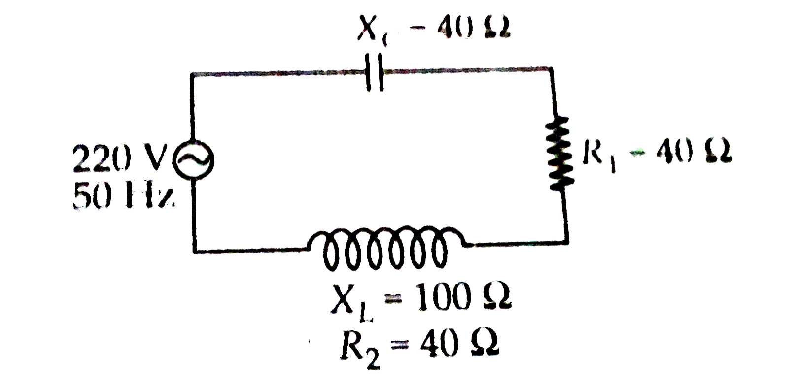
The power factor of the circuit as shown in figure is
 A0.2B0.4C0.8D0.6
The average power dissipation in a pure capacitance in AC circuit is
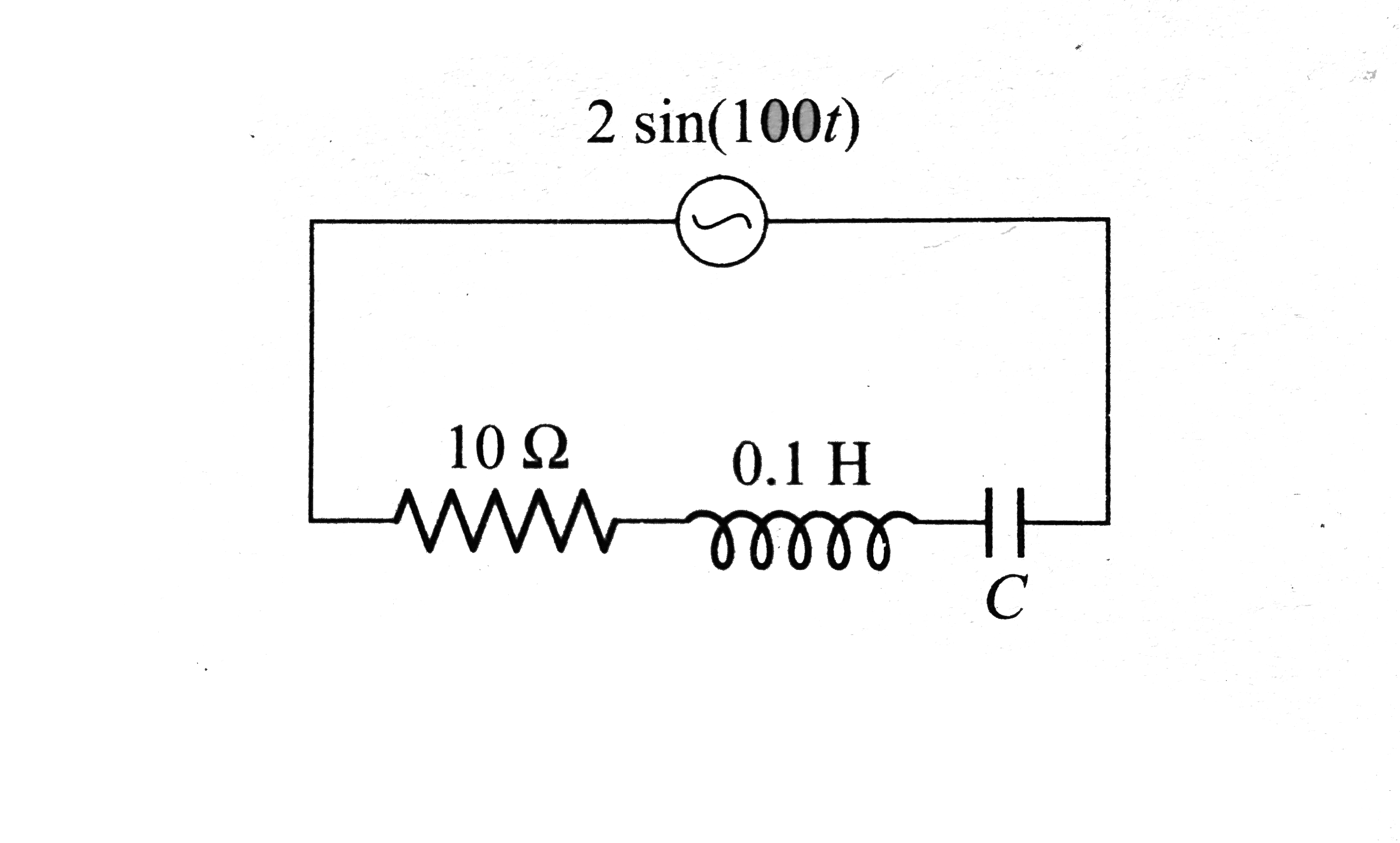
View SolutionPower factor of the circuit shown here is

View SolutionThe power factor of a circuit is
View SolutionThe power factor of the circuit in fig. is 1/√2. The capacitance of the circuit is equal to

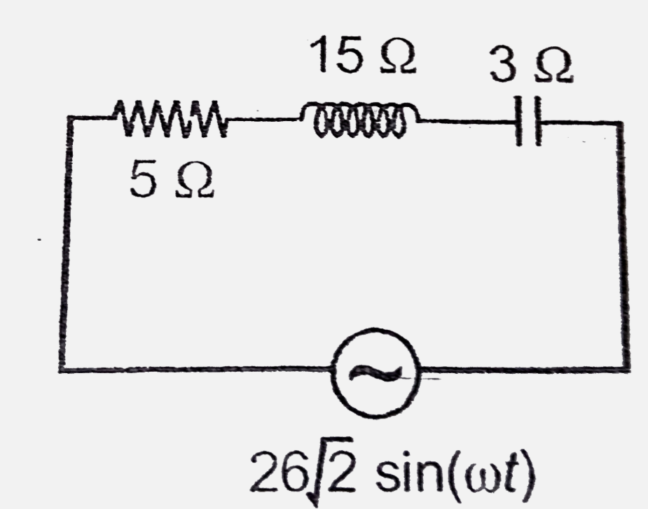
View SolutionFind average power loss in the following RLC circuit

View SolutionIn an AC circuit, the power factor
View SolutionIn an AC circuit, the power factor
View Solution