A rod AB of mass M and length L is shown in figure. End A of rod is hinged and end B is lying on the ground. Find the
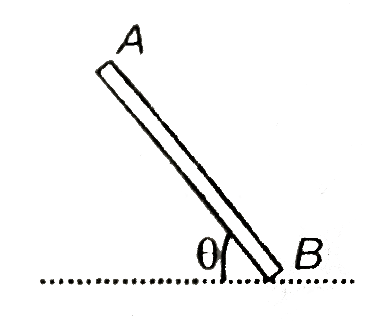
Normal reaction by ground on the rod
mg
mg2
3mg2
Cannot be determined
Step by step video & image solution for A rod AB of mass M and length L is shown in figure. End A of rod is hinged and end B is lying on the ground. Find the Normal reaction by ground on the rod by Physics experts to help you in doubts & scoring excellent marks in Class 12 exams.
Updated on:21/07/2023Topper's Solved these Questions
- SYSTEM OF PARTICLES AND ROTATIONAL MOTIONBOOK - AAKASH INSTITUTECHAPTER - SYSTEM OF PARTICLES AND ROTATIONAL MOTIONEXERCISE - Assignment (Section - E) Assertion-Reason Type Questions
12 Videos
- SYSTEM OF PARTICLES AND ROTATIONAL MOTIONBOOK - AAKASH INSTITUTECHAPTER - SYSTEM OF PARTICLES AND ROTATIONAL MOTIONEXERCISE - Assignment (Section - F) Matrix-Match Type Questions
8 Videos
- SYSTEM OF PARTICLES AND ROTATIONAL MOTIONBOOK - AAKASH INSTITUTECHAPTER - SYSTEM OF PARTICLES AND ROTATIONAL MOTIONEXERCISE - Assignment (Section - C) Objective Type Questions (More than one option are correct)
28 Videos
- SEMICONDUCTOR ELECTRONICS: MATERIALS, DEVICES AND SIMPLE CIRCUITSBOOK - AAKASH INSTITUTECHAPTER - SEMICONDUCTOR ELECTRONICS: MATERIALS, DEVICES AND SIMPLE CIRCUITSEXERCISE - Assignment (Section-D (Assertion and reason))
5 Videos
- TEST 1BOOK - AAKASH INSTITUTECHAPTER - TEST 1EXERCISE - EXERCISE
9 Videos
Similar Questions
A rod AB of mass M and length L is shown in figure. End A of rod is hinged and end B is lying on the ground. Find the
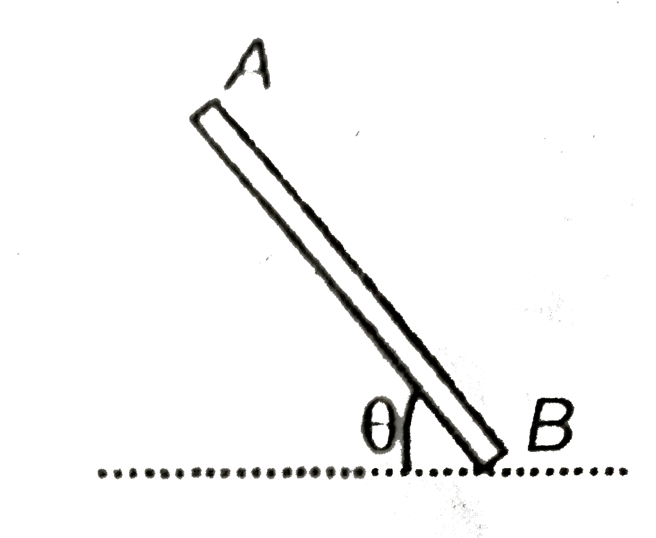
Vertical component of the force applied by the hinge
View SolutionA rod AB of mass M and length L is shown in figure. End A of rod is hinged and end B is lying on the ground. Find the
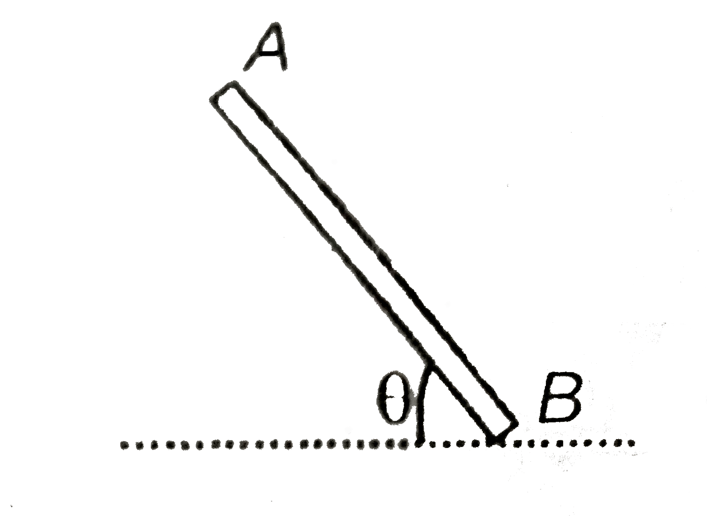
Horizontal component of the force applied by the hinge
View Solution
Knowledge Check
A rod of mass m and length l is hinged at 'its' end and released from rest in position shown. Find the force exerted by the hinge when the rod becomes horizontal
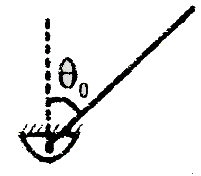 Amg4B3mg2cosθCmg4√9cos2θ+14Dmg2√9cos2θ+14
A rod AB is shown in figure. End A of the rod is fixed on the ground. Block is moving with velocity 2ms−1 towards right. The velocity of end B of rod at the instant shown in figure is
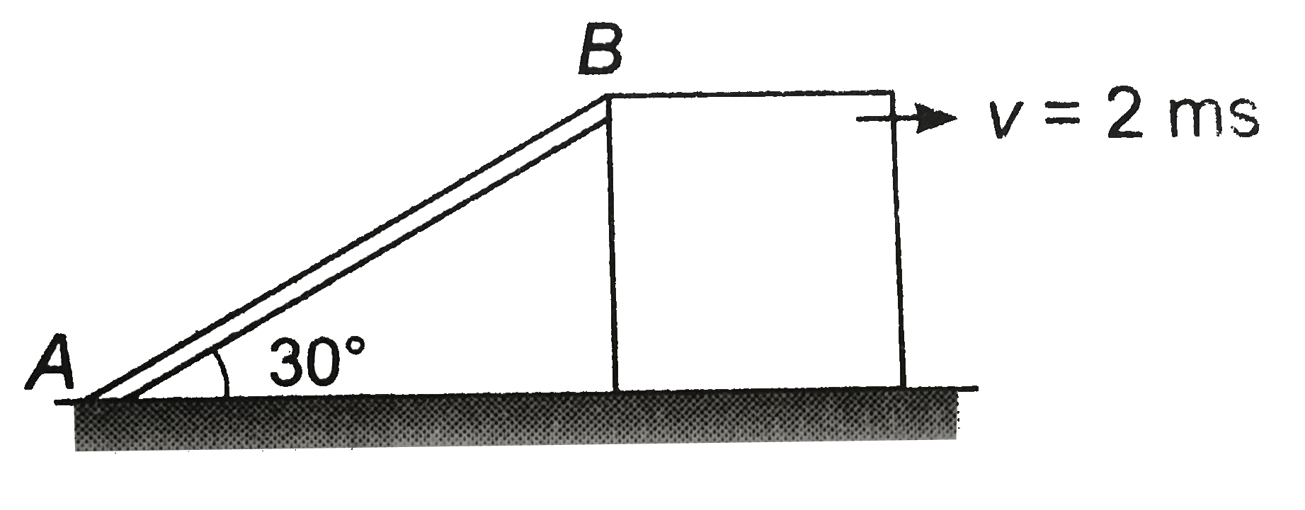 A√3ms−1B2ms−1C2√3ms−1D4ms−1
A rod AB of mass M and length L lies on smooth horizontal table impulse J is applied to end A as shown in the figure immediately after imparting the impulse :
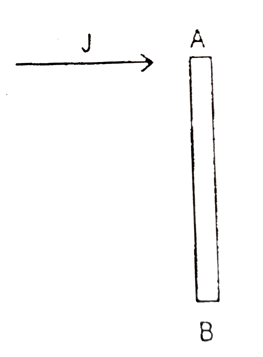 AThe radius of curvature of trajectory of A as seen from the ground is 89L.BThe radius of curvature of trajectory of B as seen from the ground is 29L.CThe instantaneous axis of rotation is at a distance of L/6 from the mid point of the rod.Dthe mid point of the rod will move along a straight line.
A uniform rod of mass M and length L is hinged at its end. The rod is released from its vertical position by slightly pushing it. What is the reaction at the hinge when the rod becomes horizontal, again vertical.
View SolutionA uniform rod AB of mass m and length l is at rest on a smooth horizontal surface. An impulse J is applied to the end B perpendicular to the rod in horizontal direction. Speed of the point A of the rod after giving impulse is:
View SolutionA rod of mass M and length L is placed on a smooth horizontal surface. It is hinged at one end so that it can rotate freely in a horizontal circle about this end. There exists a uniform magnetic field →B perpendicular, into the horizontal surface everywhere. The strength of magnetic field starts varying as B=B0t.
(i) Find the torque acting on the rod about its hinged end.
(ii) Find the reaction produced at hinge at t = 0.
(A charge Q is distributed uniformaly on the rod)
View SolutionA rod of mass m and length l is lying on a horizontal table. Work done in making it stand on one end will be
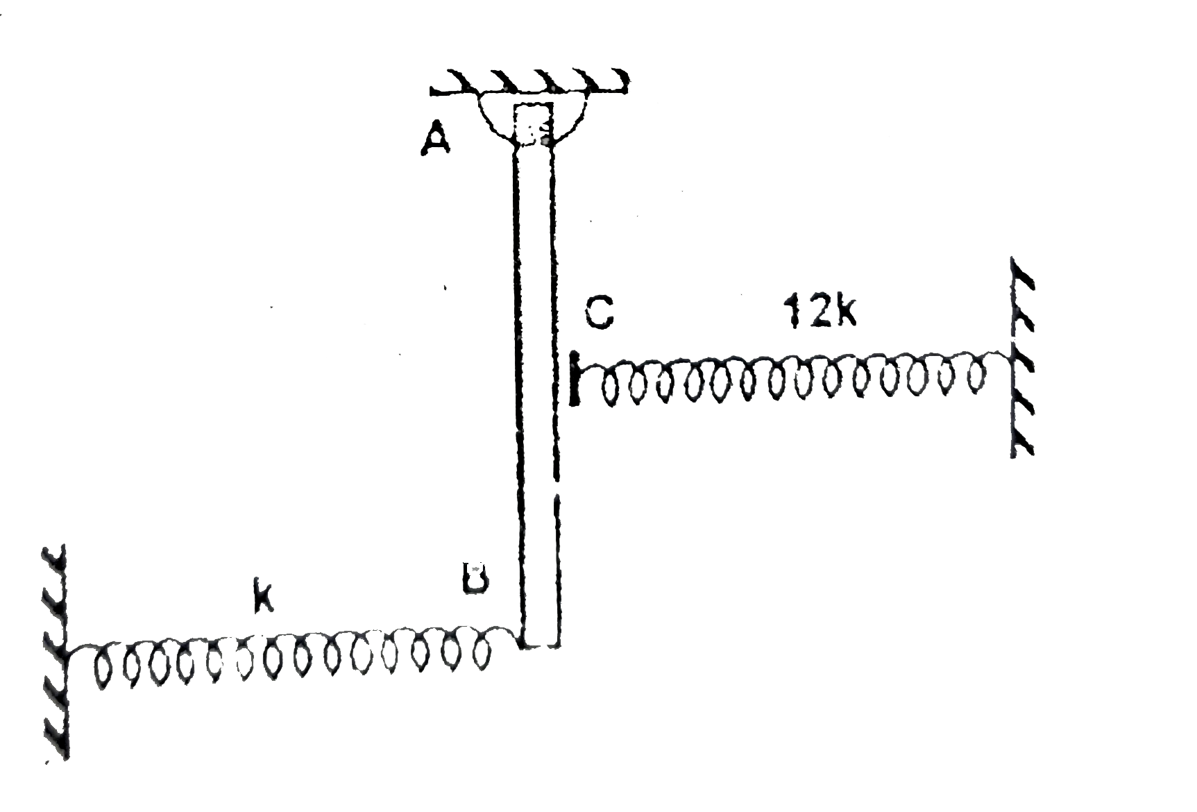
View SolutionA rod of mass m and length L is kept on a horizontal smooth surface. The rod is hinged at its one end A. There are two springs, perpendicular to the rod, kept in the same horizontal plane. The spring of spring constant k is rigidly attached to the lower end of rod and spring of spring constant 12k just touches the rod at its midpoint C, as shown in the figure. If the rod is slightly displaced leftward and released then, the time period for small osciallation of the rod will be
View Solution
