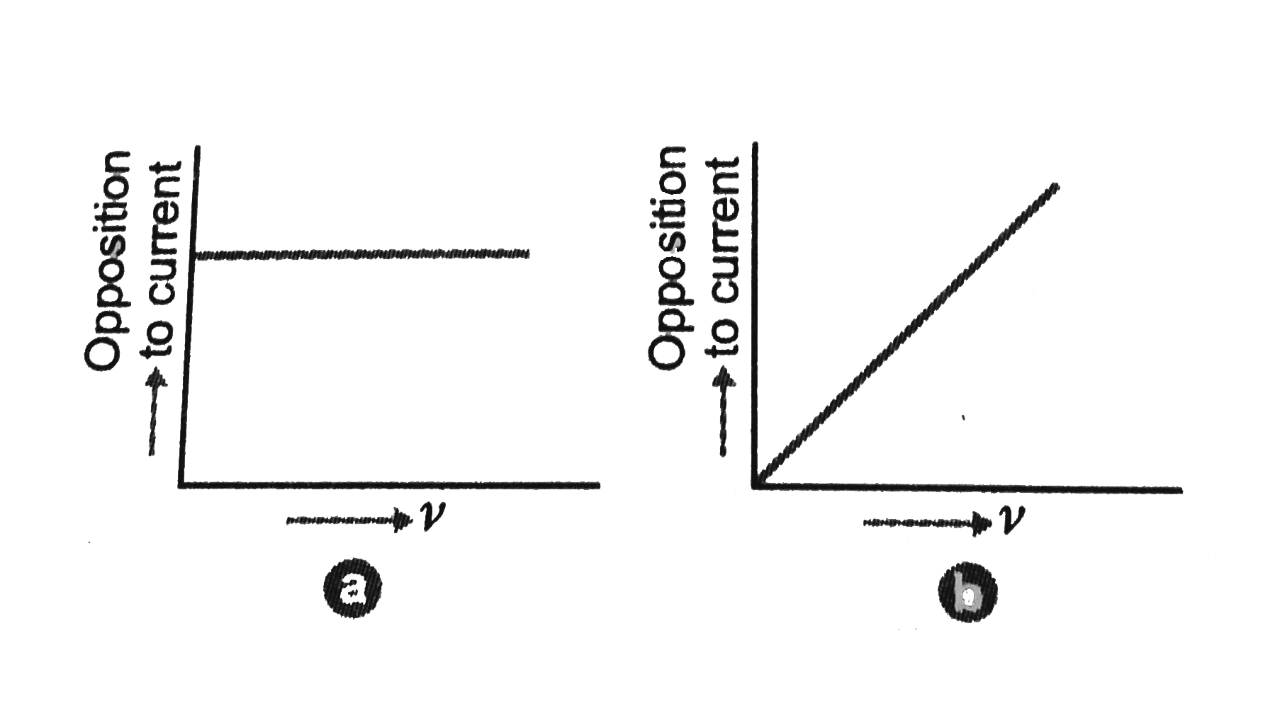
(a) The graphs (i) and (ii) shown in the Fig. 7.30 represent variation of opposition offered by the circuit elements, X and Y, respectively to the flow of alternating current versus the frequency of the applied emf. Identify the elements X and Y.
(b) Write the expression for the impedance offered by the series combination of these two elements connected to an a.c. source of voltage V=Vmsinωt. Show on a graph the variation of the voltage and the current with 'wť in the circuit.

(a) The circuit element X is a resistance R because opposition offered by it for flow of an a.c. is independent of frequency. The circuit element Y is a capacitor, as the opposition offered by it for flow of an a.c. decreases with increase in frequency.
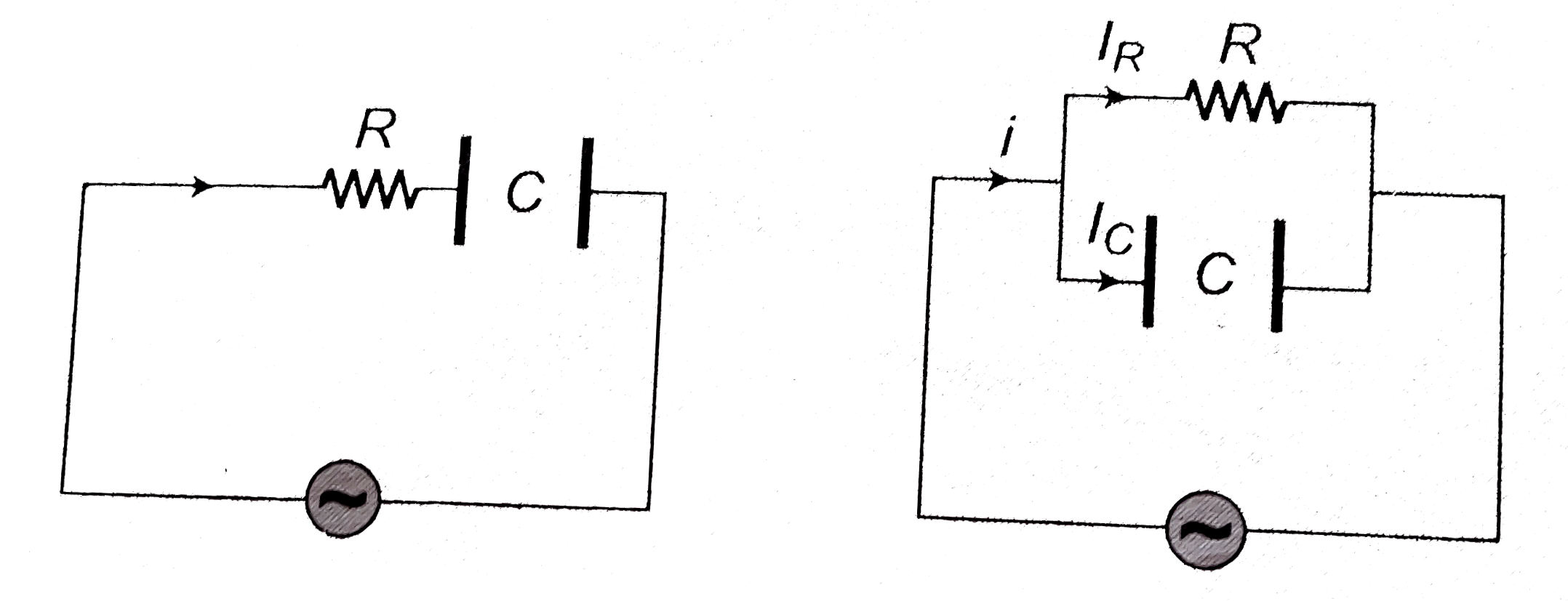
(b) For an RC circuit in series the impedance Z is given as
Z=√R2+X2L, wheer XC=1Cω
Variation of V and I for the circuit with .ωt is given in Fig.

Topper's Solved these Questions
- ALTERNATING CURRENT BOOK - U-LIKE SERIESCHAPTER - ALTERNATING CURRENT EXERCISE - LONG ANSWER QUESTIONS -II
12 Videos
- ALTERNATING CURRENT BOOK - U-LIKE SERIESCHAPTER - ALTERNATING CURRENT EXERCISE - SELF ASSESSMENT TEST (SECTION -A) (MULTIPLE CHOICE QUESTIONS)
4 Videos
- ALTERNATING CURRENT BOOK - U-LIKE SERIESCHAPTER - ALTERNATING CURRENT EXERCISE - SHORT ANSWER QUESTIONS
32 Videos
- ATOMSBOOK - U-LIKE SERIESCHAPTER - ATOMSEXERCISE - SELF ASSESSMENT TEST (SECTION C)
2 Videos
Similar Questions
(a) The graphs (i) and (ii) represent the variation of the opposition offered by the circuit elements to the flow of alternating current with frequency of the applied emf. Identify the circuit element corresponding to each graph.
(b) Write the expression for the impedance offered by the series combination of above two elements connected across the a.c. source. Which will be ahead in phase in this circuit, voltage or current ?
View SolutionThe graphs shown in Fig. represent the variation of opposition offered by the circuit element of the flow of a.c. with frequency of applied e.m.f. Iddntify the circuit element .

View Solution
Knowledge Check
An AC source producing emf V=V0 "["sin omega t+sin 2omegat"]" is connected in series with a capacitor and a resistor. The current found in the circuit is
Ai1−i2Bi1<i2Ci1>i2Di1 may be less than, equal to or greater than i2An alternating current by frequency v is flowing in a circuit containing a resistance R and inductance L in series. The impedance of this circuit is
AR = 2πvLB√R2+4π2v2L2C√R2+L2D√R2+2πvLA capacitor of capacity C is connected in A.C circuit. If the applied emf is V=V0sinωt, then the current is
AI=V0LωsinωtBI=V0ωCsin(ωt+π2)CI=V0CωsinωtDt=V0Cωsin(ωt+π2)
An electrical element X when connected to an alternating voltage source has current through it leading the voltage by π/2 radian. Identify X and write an expression for its reactance.
View SolutionSketch a graph showing the variation of impedance of LCR circuit the frequency of applied voltage.
View SolutionFor a resistance R and capacitance C in series the impedance is twice that of a parallel combination of the same elements What is the frequency of applied emf .
 .
.
View SolutionFor a resistance R and capacitance C in series the impedence is twice that of a parallel combinations of the same elements. The frequency of the applied emf shall be
View SolutionFor a resistance R and capacitance C in series the impedence is twice that of a parallel combinations of the same elements. The frequency of the applied emf shall be
View Solution
