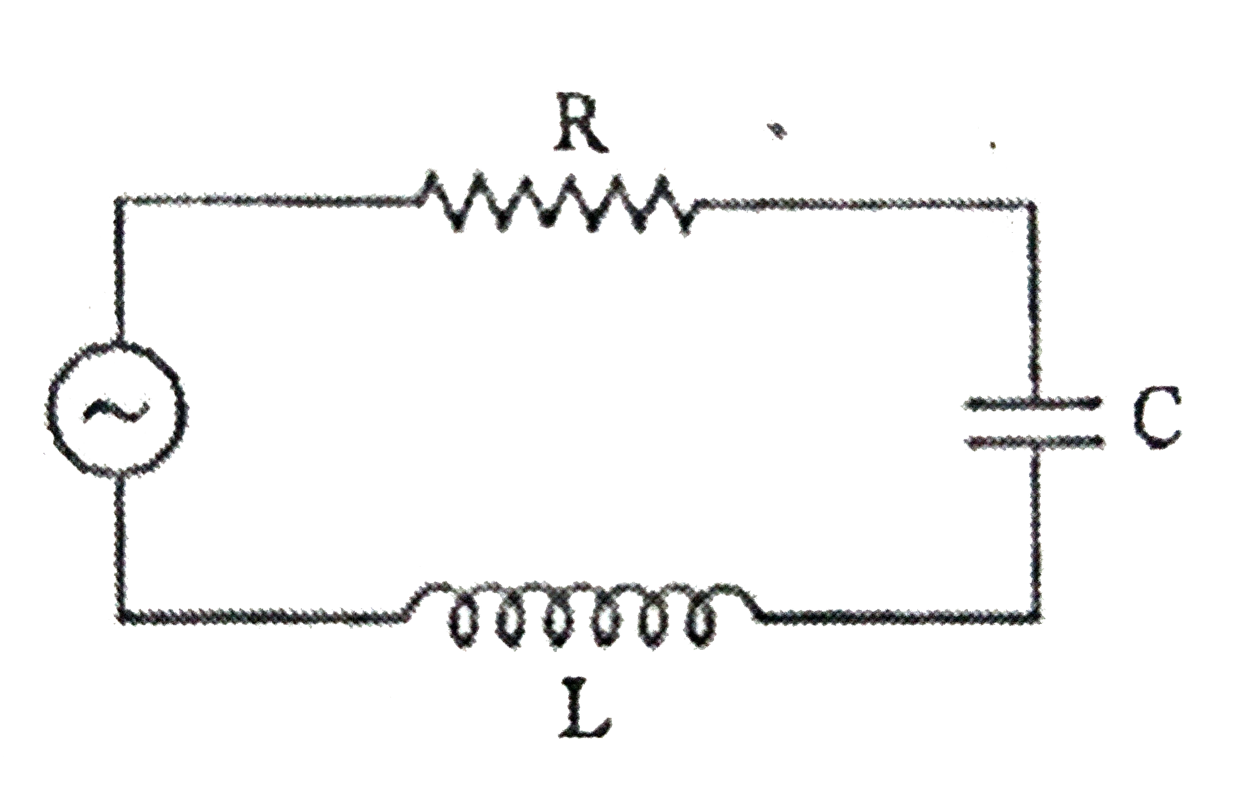
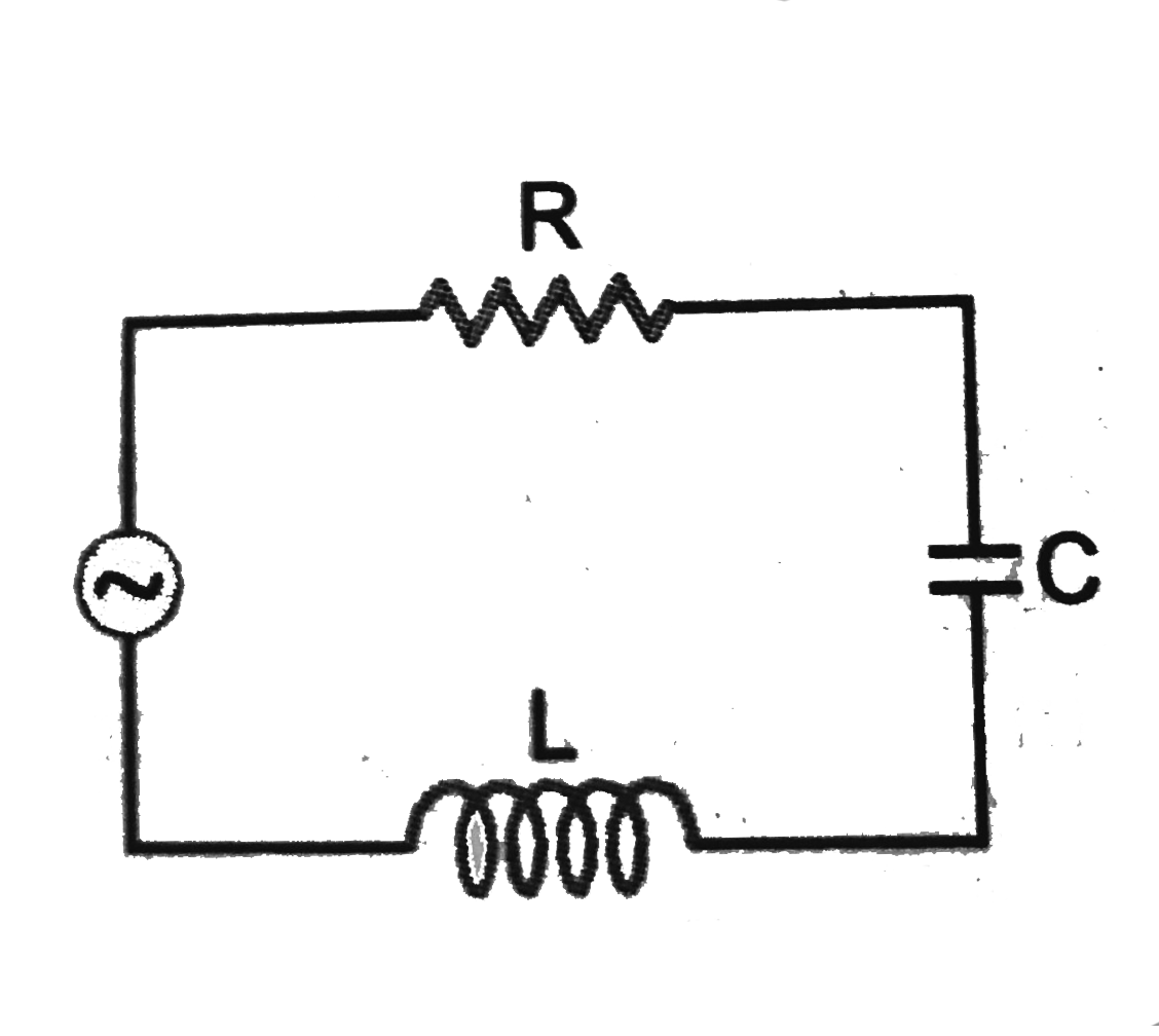
The figure 7.37 shows a series LCR circuit L = 5.0 H, C = 80 uF, R= 40 Ω connected to a variable frequency 240 V source. Calculate
(i) The angular frequency of the source which drives the circuit at resonance.
(ii) The current at the resonating frequency.
(iii) The rms potential drop across the capacitor at resonance.

As per question L = 5.0 H, C = 80 μF=80×10−6F,R=40Ω and Vrms=240V
(i) The angular frequency for resonance ω=1√LC=1√5.0×80×10−6=50s−1
(ii) The rms value of current at resonating frequency Irms=VrmsR=24040=6A
(iii) The rms potential drop across the capacitor at resonance
VC=IXC=ICω=680×10−6×50=1500V
Topper's Solved these Questions
- ALTERNATING CURRENT BOOK - U-LIKE SERIESCHAPTER - ALTERNATING CURRENT EXERCISE - LONG ANSWER QUESTIONS -II
12 Videos
- ALTERNATING CURRENT BOOK - U-LIKE SERIESCHAPTER - ALTERNATING CURRENT EXERCISE - SELF ASSESSMENT TEST (SECTION -A) (MULTIPLE CHOICE QUESTIONS)
4 Videos
- ALTERNATING CURRENT BOOK - U-LIKE SERIESCHAPTER - ALTERNATING CURRENT EXERCISE - SHORT ANSWER QUESTIONS
32 Videos
- ATOMSBOOK - U-LIKE SERIESCHAPTER - ATOMSEXERCISE - SELF ASSESSMENT TEST (SECTION C)
2 Videos
Similar Questions
The figure shows a series LCR circuit with L=10.0H2,C=40μF,R=60Ω connected to a variable frequency 240 V source. Calculate
(i) The angular frequency of the source which drives the circuit at resonance.
(ii) The current at the resonating frequency.
(iii) The rms potential drop across the capacitor at resonance.

View SolutionThe figure shows a series LCR circuit with L=10.0H2,C=40μF,R=60Ω connected to a variable frequency 240 V source. Calculate
(i) The angular frequency of the source which drives the circuit at resonance.
(ii) The current at the resonating frequency.
(iii) The rms potential drop across the capacitor at resonance.

View Solution
Knowledge Check
Figure shows a series LCR circuit connected to a variable frequency 230 V source.

The source frequency which drives the circuit the circuit in resonance isA4 HzB5 HzC6 HzD8 HzFigure shows a series LCR circuit connected to a variable frequency 230 V source.

The source frequency which drives the circuit the circuit in resonance isA4 HzB5 HzC6 HzD8 Hz
Fig. shows series LCR circuit with L=5.0H,C=80μF,R=40Ω connected to a variable frequency 240 V source. Calculate
(i) the angular frequency of the source which drives the circuit at resonance.
(ii) Current at the resonating frequency.
(iii) the rms pot. drop across the capacitor at resonance.

View SolutionFig. shows series LCR circuit with L=5.0H,C=80μF,R=40Ω connected to a variable frequency 240 V source. Calculate
(i) the angular freuquency of the source which drives the circuit at resonance.
(ii) Current at the resonanting frequency.
(iii) the rms pot. drop across the capacitor at resonance.

View SolutionA series LCR circuit with L=4.0H,C=100μF and R=60Ω is connected to a variable frequency 240 V source. Calculate
(i) angular frequency of the source which drives the circuit in resonance,
(ii) current at the resonating frequency,
(iii) rms potential drop across the inductance at resonance.
View SolutionA series LCR circuit with L=4.0h,C=100μF and R=60Ω is connected to a varialbe frequency 240 V source. Calcalate
(i) angular frequency of the source which drives the circuit in resonace,
(ii) current at the resonating frequency,
(iii) rms potential drop across the inductro at resonance.
View SolutionA series LER circuit with C=80μF, L = 5.0 H and R=40Ω is connected to a variable frequency 240 V a.c. source Calculate
(i) angular frequency of the source which drives the circuit in resonanace.
(ii) current at the resonating frequency.
(iii) rms pot. drop across the capacitor.
View SolutionA series LCR circuit with L=80mH,C=50μF and R=60ohm is connected to a variable frequency 220 V source. Determine (i) the source frequency which drives the circuitin resonance (iii) the quality factor Q of the circuit.
View Solution
