(A) : The resistance of voltmeter is very small as compared to the resistance of the galvanometer, from which it is obtained.
(R) : The voltmeter is connected in series to the conductor across which potential difference is to be measured.
Both 'A' and 'R' are true and 'R' is the correct explanation of 'A'.
Both 'A' and 'R' are true and 'R' is not the correct explanation of 'A'
'A' is true and 'R' is false
'A' is false and 'R' is false
The correct Answer is:D
To solve the question, we need to analyze the statements (A) and (R) regarding the voltmeter and the galvanometer.
1. Understanding Statement (A):
- The statement claims that "The resistance of a voltmeter is very small as compared to the resistance of the galvanometer, from which it is obtained."
- This statement is incorrect. A voltmeter is designed to have a high resistance to ensure that it does not draw significant current from the circuit it is measuring. This allows it to measure the potential difference without affecting the circuit.
2. Understanding Statement (R):
- The statement claims that "The voltmeter is connected in series to the conductor across which potential difference is to be measured."
- This statement is also incorrect. A voltmeter should be connected in parallel to the circuit element across which the voltage is to be measured. If it is connected in series, it would alter the current flowing through the circuit, leading to an inaccurate measurement.
3. Conclusion:
- Since both statements (A) and (R) are incorrect, we conclude that both the assertion and the reason are false.
Final Answer:
Both statements (A) and (R) are false.
- The statement claims that "The resistance of a voltmeter is very small as compared to the resistance of the galvanometer, from which it is obtained."
- This statement is incorrect. A voltmeter is designed to have a high resistance to ensure that it does not draw significant current from the circuit it is measuring. This allows it to measure the potential difference without affecting the circuit.
- The statement claims that "The voltmeter is connected in series to the conductor across which potential difference is to be measured."
- This statement is also incorrect. A voltmeter should be connected in parallel to the circuit element across which the voltage is to be measured. If it is connected in series, it would alter the current flowing through the circuit, leading to an inaccurate measurement.
- Since both statements (A) and (R) are incorrect, we conclude that both the assertion and the reason are false.
Both statements (A) and (R) are false.
Topper's Solved these Questions
- MOVING CHARGES AND MAGNETISMBook:AAKASH SERIESChapter:MOVING CHARGES AND MAGNETISMExercise:EXERCISE-II
Explore 79 Videos
- MOVING CHARGES AND MAGNETISMBook:AAKASH SERIESChapter:MOVING CHARGES AND MAGNETISMExercise:EXERCISE-III
Explore 49 Videos
- MOVING CHARGES AND MAGNETISMBook:AAKASH SERIESChapter:MOVING CHARGES AND MAGNETISMExercise:EXERCISE-IA
Explore 142 Videos
- MOTION IN A STRAIGHT LINE Book:AAKASH SERIESChapter:MOTION IN A STRAIGHT LINE Exercise:very Short answer type question
Explore 15 Videos
- NUCLEAR PHYSICSBook:AAKASH SERIESChapter:NUCLEAR PHYSICSExercise:ADDITIONAL PRACTICE PRACTICE SHEET (ADVANCED) Integer Type Questions
Explore 3 Videos
Similar Questions
How is voltmeter connected in the circuit to measure potential difference between two points ?
View Solution(A) : Voltmeter put across a part of the circuit, it reads slightly less than the original voltage.
(R) : Voltmeter is always connected in parallel in circuit across which voltage is to be measured.
View Solution
Knowledge Check
The resistance of a galvanometer is 10Ω. It gives full-scale deflections when 1mA current is passed. The resistance connected in series for converting it into a voltmeter of 2.5V will be
A24.9ΩB249ΩC2490ΩD24900Ω
Assertion : Voltmeter is connected in parallel with the circuit
Reason : Resistance of a voltmeter is very large.
View SolutionStatement I: The resistance of an ideal voltmeter should be infinite.
Statement II: Lower resistance of voltmeters gives a reading lower than the actual potential difference across the terminals.
View SolutionWhich of the two, an ammeter or a voltmeter, has a greater resistance ?
View SolutionA battery of emf 1.4V and internal resistance 2Ω is connected to a resistor of 100ω resistance through an ammeter. This resistance of the ammeter is 4/3Ω. A voltmeter has also been connected to find the potential difference across the resistor.
a. Draw the circuit diagram.
b. The ammeter reads 0.02A. What is the resistance of the voltmeter?
c. The voltmeter reads 1.1V. What is the error in the reading?
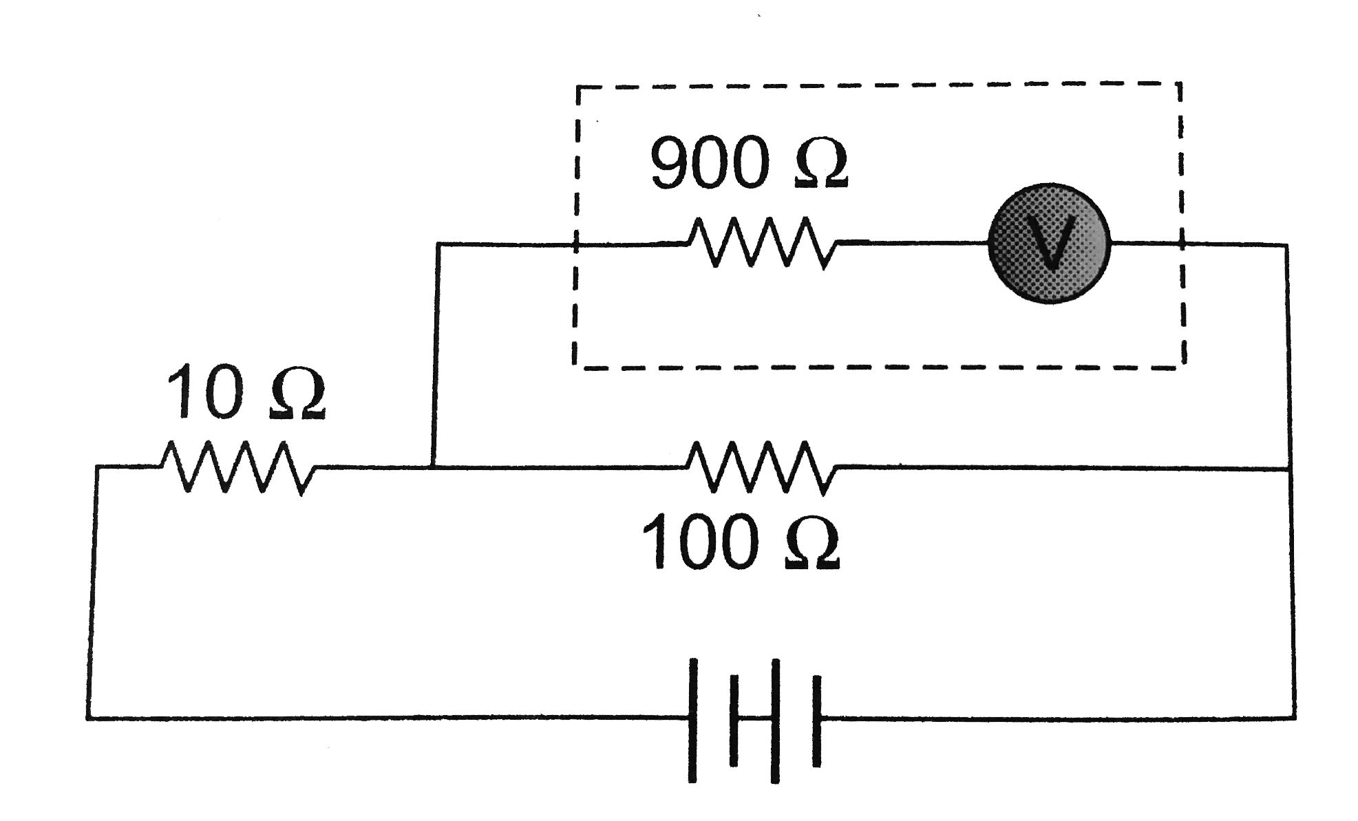
View SolutionThe potential difference across the 100Ω resistance in the following circuit is measured by a voltmeter of 900Ω resistance. The percentage error made in reading the potential difference is

View Solution(A) :· The range of given voltmeter can be both increased and decreased.
(R) : By adjusting the value of resistance in series with galvanometer the range of votlmeter can be adjusted.
View SolutionThe resistance of a galvanometer is 10Ω. It gives full-scale deflections when 1mA current is passed. The resistance connected in series for converting it into a voltmeter of 2.5V will be
View Solution