A : When tiny circular obstacle is placed in the path of light from some distance, a bright spot is seen at the centre of the shadow of the obastacle.
R : Destructive interference occurs at the centre of the shadow of circular obstacle.
Both A and R are true and R is the correct explanation of A
Both A and R are true and R is not the correct explanation of A
A is true and R is false
Both A and R are false
The correct Answer is:C
Step by step video & image solution for A : When tiny circular obstacle is placed in the path of light from some distance, a bright spot is seen at the centre of the shadow of the obastacle. R : Destructive interference occurs at the centre of the shadow of circular obstacle. by Physics experts to help you in doubts & scoring excellent marks in Class 12 exams.
Updated on:21/07/2023Topper's Solved these Questions
- WAVES OPTICSBOOK - AAKASH SERIESCHAPTER - WAVES OPTICSEXERCISE - EXERCISE -II (INTERFERENCE)
26 Videos
- WAVES OPTICSBOOK - AAKASH SERIESCHAPTER - WAVES OPTICSEXERCISE - EXERCISE -II (DIFFRACTION)
17 Videos
- WAVES OPTICSBOOK - AAKASH SERIESCHAPTER - WAVES OPTICSEXERCISE - EXERCISE -IA (ASCENDING AND DSCENDING ORDER TYPE QUESTIONS)
6 Videos
- WAVESBOOK - AAKASH SERIESCHAPTER - WAVESEXERCISE - EXERCISE-III (Doppler effect :)
15 Videos
Similar Questions
A: When a tiny circular obstacle is placed in the path of light from a distant source, a bright spot is seen at the centre of the shadow of the obstacle.
R: Waves diffracted from the edge of the circular obstacle interfere constructively at the centre of the shadow producing a bright spot.
View SolutionIn a singleslit diffraction experiment, when a tiny circular obstacle is placed in the path of light from a distant source, a bright spot is seen at the centre of the shadow of the obstacle. Explain why ?
State two points of difference the interference pattern obtained in Young's double slit experiment and the diffraction pattern due to a single slit.
View Solution(a) Define a wavefront. Using Huygen's principle, verify the laws of reflection at a plane surface .
(b) In a single slit diffraction experiment the wildth of the slit is made double the orignal width.
How does this affect the size and intensity of the central diffraction band ? Explain.
(c) When a tiny circular obstacle in placed in the path of light from a distance source, a bright spot is seen at the centre of the obstacle . Explain why.
View SolutionOn a particle moving on a circular path with constant speed v, light is thrown from a projectors placed at the centre of the circular path. The shadow of the particle is formed on the wall. The velocity of shadow up the wall is

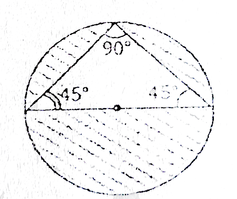
View SolutionFrom a circular disc of radius R, a triangular portion is cut (sec figure). The distance of the centre of mass of the remainder from the centre of the disc is −

View SolutionA circular coil of radius 2R is carrying current 'i' . The ratio of magnetic fields at the centre of the coil and at a point at a distance 6R from the centre of the coil on the axis of the coil is
View SolutionInterference fringes were produced using light in a doulbe-slit experiment. When a mica sheet of uniform thickness and refractive index 1.6 (relative to air) is placed in the path of light from one of the slits, the central fringe moves through some distance. This distance is equal to the width of 30 interference bands if light of wavelength 4800 is used. The thickness (in μm) of mica is
View SolutionA circular current carrying coil has a radius R. The distance from the centre of the coil on the axis where the magnetic induction will be 18 th to its value at the centre of the coil, is
View SolutionA circular current carrying coil has a radius R. The distance from the centre of the coil on the axis where the magnetic induction will be (1/8)th of its value at the centre of the coil is,
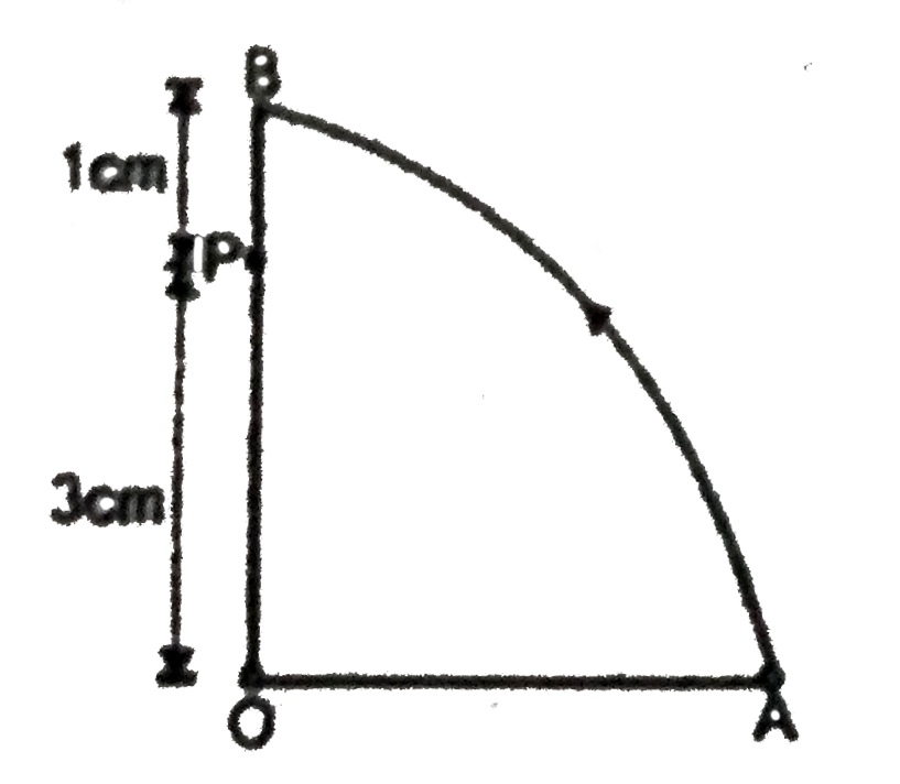
View SolutionA point charge of 5C is placed at point P (as shown in figure). A unit positive charge is taken from A to B along the circular path shown, then the net work done by electrostatic force is : [O is the centre of the circular path] [Where k=9×10⁹Nm2/C2]

View Solution
