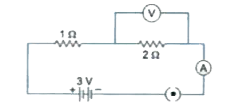
Compare how an ammeter and a voltmeter are connected in a circuit.
Video Solution
|
Answer
Step by step video & image solution for Compare how an ammeter and a voltmeter are connected in a circuit. by Physics experts to help you in doubts & scoring excellent marks in Class 10 exams.
Updated on:21/07/2023Topper's Solved these Questions
- ELECTRICITY BOOK - LAKHMIR SINGH & MANJIT KAURCHAPTER - ELECTRICITY EXERCISE - Very Short Answer Type Questions
1 Videos
- ELECTRICITY BOOK - LAKHMIR SINGH & MANJIT KAURCHAPTER - ELECTRICITY EXERCISE - Short Answer Type Questions
2 Videos
- ELECTRICITY BOOK - LAKHMIR SINGH & MANJIT KAURCHAPTER - ELECTRICITY EXERCISE - Sample Problem
1 Videos
- MAGNETIC EFFECT OF ELECTRIC CURRENT BOOK - LAKHMIR SINGH & MANJIT KAURCHAPTER - MAGNETIC EFFECT OF ELECTRIC CURRENT EXERCISE - NCERT BOOK
2 Videos
Similar Questions
Knowledge Check
An ammeter and a voltmeter are connected in series to an ideal battery of emf E. If the ammeter reads I and voltmeter reading V, then
AV<εBthe resistance of voltmeter is V/ICP.D. across the ammeter is E-VDAmmeter and voltmeter have equivalent resistance = E/lA voltmeter and an ammeter are connected in the circuit as shown. Resistance of ammeter is say R10 and that of voltmeter is 10R. Then
 Apercentage error in the reading of ammeter (compared to that measured, if both ammeter and voltmeter were ideal) is - 1.0%Bpercentage error in the reading of voltmeter is - 10.0%Cboth (a) and (b) are correctDboth (a) and (b) wrong
STATEMENT-1: Out of galvanometer, ammeter an voltmeter, resistance of ammeter is lower and resistance of voltmeter is highest because
STATEMENT-2: An ammeter is connected in series and a voltmeter is connected in parallel, in a circuit.AStatement-1 is True , Statement-2 is True , Statement-2 is a correct explanation for Statement-1.BStatement-1 is True , Statement-2 is True , Statement-2 is NOT a correct explanation for Statement-1.CStatement-1 is True , Statement-2 is FalseDStatement-1 is False , Statement-2 is True
How is the ammeter connected in the circuit?
View SolutionA voltmeter, an ammeter and a resistance are connected in series with a lead accumulator. The voltmeter gives some deflection but the deflection of ammeter is almost zero. Explain why?
View SolutionWhat would be the reading of ammeter and voltmeter in the given circuit?

View SolutionA ciruit to verify Ohm's law uses ammeter and voltmeter in series or parallel connected correctly to the resistor. In the circuit :
View SolutionIf the positions of voltmeter and ammeter are interchanged in Ohm's law circuit, then
View Solution
