A ciruit to verify Ohm's law uses ammeter and voltmeter in series or parallel connected correctly to the resistor. In the circuit :
ammeter is always used in parallel and voltmeter is series
Both ammeterand voltmeter must be connected in parallel
ammeter is always connected in series and voltmeter in parallel
Both, ammeter and voltmeter must be connected in series
To verify Ohm's Law using a circuit with an ammeter and a voltmeter, we need to follow these steps:
1. Understanding Ohm's Law:
Ohm's Law states that the current (I) flowing through a conductor between two points is directly proportional to the voltage (V) across the two points, given by the equation V=I×R, where R is the resistance.
2. Setting Up the Circuit:
- We need to connect a resistor in the circuit.
- An ammeter (A) is used to measure the current flowing through the circuit.
- A voltmeter (V) is used to measure the voltage across the resistor.
3. Connecting the Ammeter:
- The ammeter must be connected in series with the resistor. This is because the ammeter measures the current flowing through the circuit, and for accurate measurement, it must be part of the same path as the current.
4. Connecting the Voltmeter:
- The voltmeter must be connected in parallel with the resistor. This allows the voltmeter to measure the potential difference (voltage) across the resistor directly.
5. Verifying Connections:
- Ensure that the ammeter is connected in series with the resistor and that the voltmeter is connected in parallel across the resistor.
- This configuration allows us to measure the current through the resistor and the voltage across it simultaneously.
6. Taking Measurements:
- Turn on the circuit and take readings from both the ammeter and the voltmeter.
- Record the current (I) from the ammeter and the voltage (V) from the voltmeter.
7. Plotting the Graph:
- To verify Ohm's Law, plot a graph of voltage (V) on the y-axis against current (I) on the x-axis.
- According to Ohm's Law, this should yield a straight line, indicating a linear relationship between voltage and current.
8. Conclusion:
- If the graph is a straight line, it confirms that the resistor obeys Ohm's Law, and the relationship V=I×R holds true.
Final Answer:
The correct connections are:
- Ammeter: Connected in series with the resistor.
- Voltmeter: Connected in parallel with the resistor.
Ohm's Law states that the current (I) flowing through a conductor between two points is directly proportional to the voltage (V) across the two points, given by the equation V=I×R, where R is the resistance.
- We need to connect a resistor in the circuit.
- An ammeter (A) is used to measure the current flowing through the circuit.
- A voltmeter (V) is used to measure the voltage across the resistor.
- The ammeter must be connected in series with the resistor. This is because the ammeter measures the current flowing through the circuit, and for accurate measurement, it must be part of the same path as the current.
- The voltmeter must be connected in parallel with the resistor. This allows the voltmeter to measure the potential difference (voltage) across the resistor directly.
- Ensure that the ammeter is connected in series with the resistor and that the voltmeter is connected in parallel across the resistor.
- This configuration allows us to measure the current through the resistor and the voltage across it simultaneously.
- Turn on the circuit and take readings from both the ammeter and the voltmeter.
- Record the current (I) from the ammeter and the voltage (V) from the voltmeter.
- To verify Ohm's Law, plot a graph of voltage (V) on the y-axis against current (I) on the x-axis.
- According to Ohm's Law, this should yield a straight line, indicating a linear relationship between voltage and current.
- If the graph is a straight line, it confirms that the resistor obeys Ohm's Law, and the relationship V=I×R holds true.
The correct connections are:
- Ammeter: Connected in series with the resistor.
- Voltmeter: Connected in parallel with the resistor.
Topper's Solved these Questions
Similar Questions
Knowledge Check
When an ammeter is connected in parallel the resistance of the circuit is
AincreasedBdecreasedCis unchangedDnone of theseAn inductor and a resistor are connected in series with an ac source. In this circuit.
Athe current and the PD across the resistance lead the PD across the inductanceBthe current and the PD across the resistance lag behind the PD across the inductance by an angle (π)/(2).Cthe current and the PD across the resistance lag behind the PD across the inductance by an angle (π).Dthe PD across the resistance lag behind the PD across the inductance by an angle (π)/(2) but the current in resistance leads the PD across the inductance by (π)/(2).By mistake a voltmeter is connected in series an an ammeter is connected in parallel with a resistance in an electrical circuit. What will happen to the instrument?
AVoltmeter is damagedBAmmeter is damagedCBoth are damagedDNone is damaged
Why is an ammeter connected in series in an electric circuit?
View SolutionCircuit Problems| Ammeter| Voltmeter
View SolutionBy mistake, a voltmeter is connected in series and an ammeter is connected in parallel, with a resistance in an electrical circuit. What will happen to the instruments?
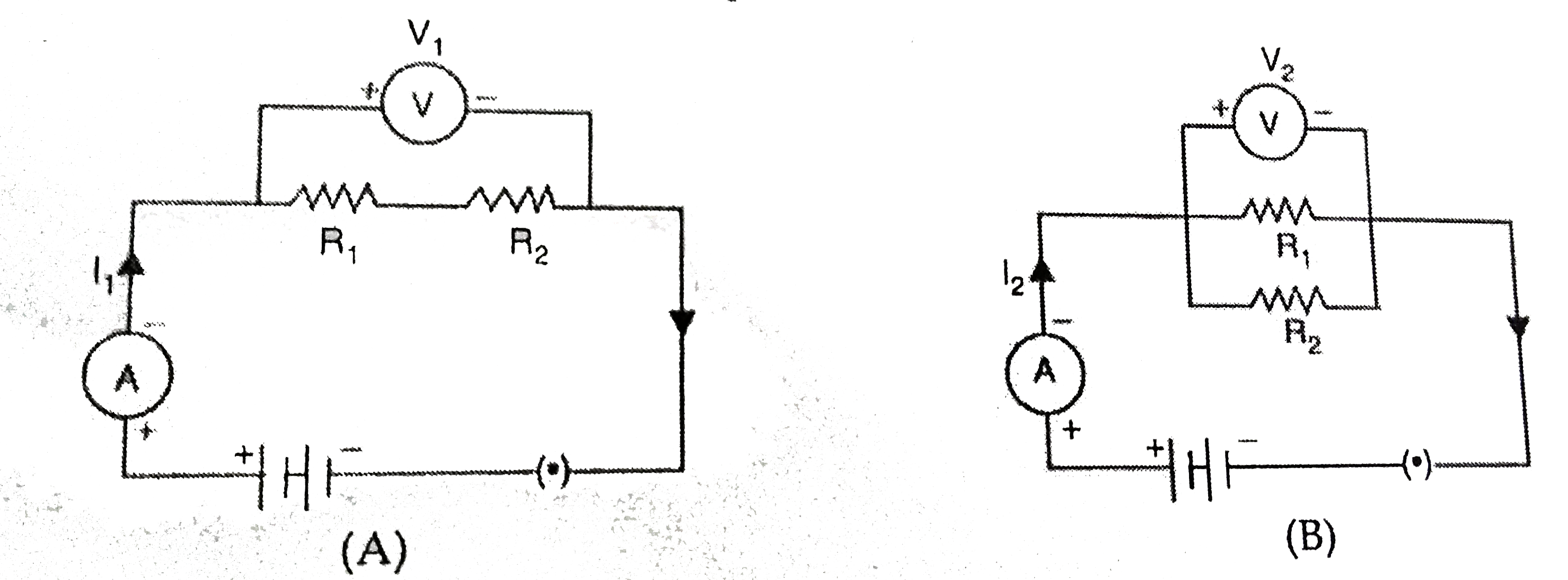
View SolutionA student using the same two resistors, ammeter, voltmeter and battery, sets up two circuits A and B connecting the two resistors first in series and then in parallel.

If the ammeter and voltmeter readings in the two cases be I1,I2 and V1,V2 respectively, he is likely to observe that :
View SolutionIn the experiment on finding the equivalent resistance of two resistors connected in series, three students connected the ammeter in their circuits in the three ways X, Y and Z shown here.

Assuming their ammeters to be ideal, the ammeters have been correctly connected in
View Solution
