Draw a schematic sketch of an generator describing its basic elements. State briefly its working principle. Show a plot of variation of
(i) Magnetic flux and
(ii) Alternating emf versus time generated by a loop of wire rotating in a magnetic field.
(b) Why is choke coil needed in the use of fluorescent tubes with ac mains?
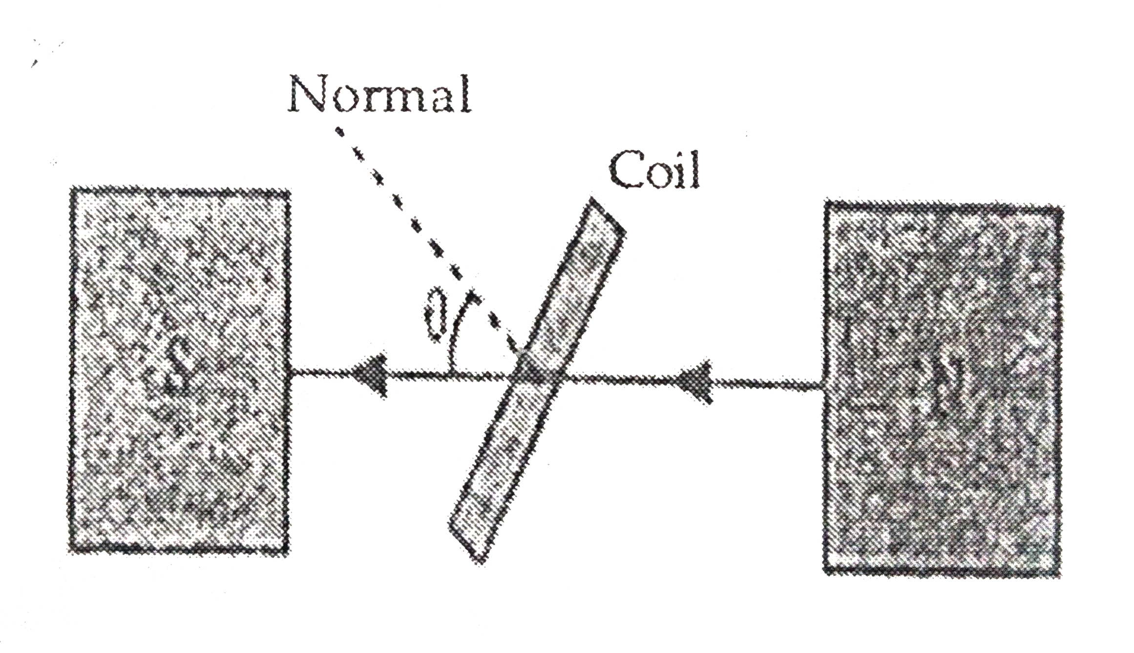
Working ''As the armature coil is rotated in the magnetic field, angle ϕ between the field and the normal to the coil changes continuously. Therefore, magnetic flux linked with the coil changes and an emf is induced in the coil. According to fleming's right hand rule, current is induced from A to B in AB and from C to D in CD.
In the external circuit, current flows from B2 to B1.
To calculate the magnitude of emf induced suppose
A→Area of each turn of the coil.
N→ Number of turns is hte coil
¯¯¯B→ Strength of the magnetic field
O→Angle which normal to the coil makes with at any instant t.

∴ Magnetic flux linked with the coil in this position is given by,
ϕ=N(B.A)
=NBAcosθ=NBAcosωt ...(i)
where 'ω' is angular velocity of the coil.
Graph between magnetic flux and time, according to equation (i), is shown below:
(ii) As the coil rotates, angle e changes. Therefore, magnetic flux θ linked with the coil change and an emf is induced in the coil. At this instant t, if e is the emf induced in the coil, then
e=−dθdt=−(d)(dt)(NABcosωθ)=−NABddt(cosωt)
=−NAB(−sinωt)ω
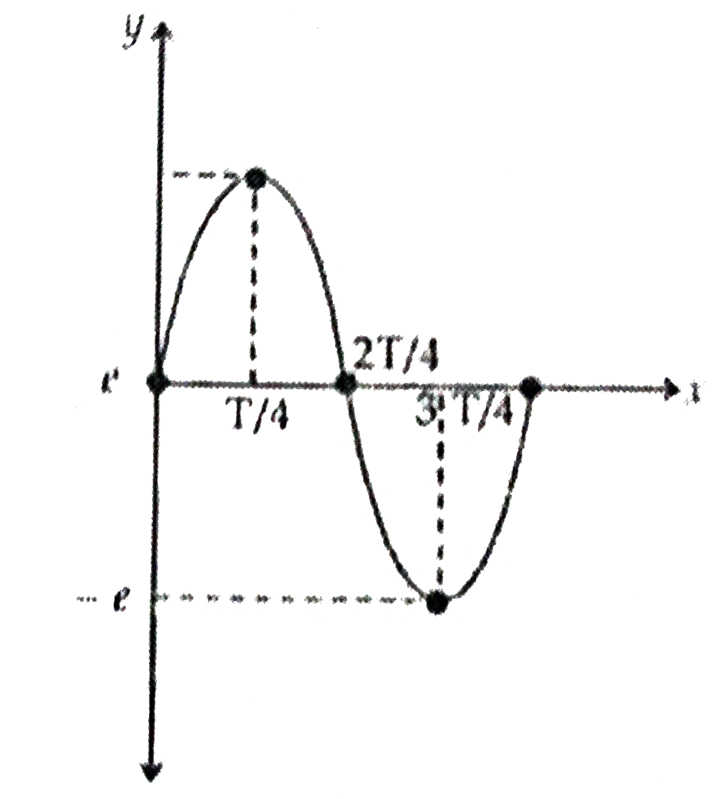
e=NABωsinωt
(iii) The graph between alternating emf versus time is shown below :

(b) A chock coil is an electrical appliance used for controlling current in an a.c. circuit. Therefore, if we use a resistance R for the same purpose, a lot of energy would be wasted in the form of heat etc.
Topper's Solved these Questions
- XII BOARDSBOOK - XII BOARDS PREVIOUS YEARCHAPTER - XII BOARDSEXERCISE - [SET - II DELHI BOARD]
6 Videos
- XII BOARDSBOOK - XII BOARDS PREVIOUS YEARCHAPTER - XII BOARDSEXERCISE - [SET - III, DELHI BOARD]
6 Videos
- XII BOARDSBOOK - XII BOARDS PREVIOUS YEARCHAPTER - XII BOARDSEXERCISE - SET - III (Delhi Board)
8 Videos
- SAMPLE PAPER 2019BOOK - XII BOARDS PREVIOUS YEARCHAPTER - SAMPLE PAPER 2019EXERCISE - SECTION D
6 Videos
Similar Questions
Draw a schematic sketch of an ac generator describing its basic elements. State briefly its working principle. Show a plot of variation of Magnetic flux
View Solution(a) Draw a schematic diagram of an AC generator. Explain is working and obtain the expression for the instantaneous value of the emf in terms of the magnetic field B, number of turns N of the coil of area A rotating with angular frequency ω. Show how an alternating emf is generated by loop of wire rotating in a magnetic field.
(b) A circular coil of radius 10 cm and 20 turns is rotated about its vertical diameter with angular speed of 50 rad s−1. in a uniform horizontal magnetic field of 3.0×10⁻²T.
(i) Calculate the maximum and average emf induced in the coil.
(ii) If the coil forms a closed loop of resistance 10Ω, calculate the maximum current in the coil and the average power loss due to Joule heating.
View SolutionDescribe briefly, with the help of a labell diagram, the basic elements of an A.C. generator. State its underlying principle. Show diagrammatically how an alternating emf is generated by a loop of wire rotating in a magnetic field. Write the expression for the instantaneous value of emf induced in the rotating loop.
View SolutionDescribe briefly, with the help of a labelled diagram, the basic elements of an a.c generator. State its underlying principle. Show diagrammatically how an alternating emf is generated by a loop of wire rotating in a magnetic field. Write the expression for the instantaneous value of the emf induced in the rotating loop.
View SolutionDescribe brifly, with the help of a labelled diagram, the basic elements of an A.C. generator.State its underlying princilple.Show diarammatically how an alternating emf is generated by a loop of wire rotating in a magnetic field.Write the expression for the instantaneous value of the emf induced in the rotating loop.
View SolutionAnswer the following questions :
(a) In any a.c. circuit, is the applied instantaneous voltage equal to the algebraic sum of the instantaneous voltages across the series elements of the circuit ? Is the same true for rins voltage ?
(b) A capacitor is used in the primary circuit of an induction coil.
(c) An applied voltage signal consists of a superposition of a d.c. voltage and an a.c. voltage of high frequency. The circuit consists of an inductor and a capacitor in series. Show that the d.c. signal will appear across C and the a.c. signal across L.
(d) A choke coil in series with a lamp is connected to a d.c. line. The lamp is seen to shine brightly. Insertion of an iron core in the choke causes no change in the lamp's brightness. Predict the corresponding observations if the connection is to an a.c. line.
(e) Why is choke coil needed in the use of fluorescent tubes with a.c. mains ? Why can we not use an ordinary resistor instead of the choke coil ?
View SolutionAnswer the following questions :
(a) In any a.c. circuit, is the applied instantaneous voltage equal to the algebraic sum of the instantaneous voltages acorss the series elements of the circuit ? Is the same true for r.m.s. voltage?
(b) A capacitor is used in the primary circuit of an induction coil.
(c ) An applied voltage signal consists of a superposition of a d.c. voltage and an a.c. voltage of high frequency. The circuit consists of an inductor and a capacitor in series. Show that the d.c. signal will appear across C and the a.c. signal will appear across L.
(d) A choke coil in series with a lamp is connected to a d.c. line. The lamp is seen to shine brightly. Insertion of an iron core in the choke causes no change in the lamp's brightness. Predict the corresponding observation if the connection is to an a.c. line.
(e) Why is choke coil needed in use of fluorescent tubes with ac mains ? Why can we not use an ordinary resistor instead of choke coil?
View Solution(a) Draw a schematic diagram of an AC generator. Explain is working and obtain the expression for the instantaneous value of the emf in terms of the magnetic field B, number of turns N of the coil of area A rotating with angular frequency ω. Show how an alternating emf is generated by loop of wire rotating in a magnetic field.
(b) A circular coil of radius 10 cm and 20 turns is rotated about its vertical diameter with angular speed of 50 rad s−1. in a uniform horizontal magnetic field of 3.0×10⁻²T.
(i) Calculate the maximum and average emf induced in the coil.
(ii) If the coil forms a closed loop of resistance 10Ω, calculate the maximum current in the coil and the average power loss due to Joule heating.
View Solutiona) State the principle of ac generator.
b) Explain with the help of a well labelled diagram, its working and obtain the expression for the emf generated in the coil.
c) Is it possible to generate emf without rotating the coil? Explain
View Solution
