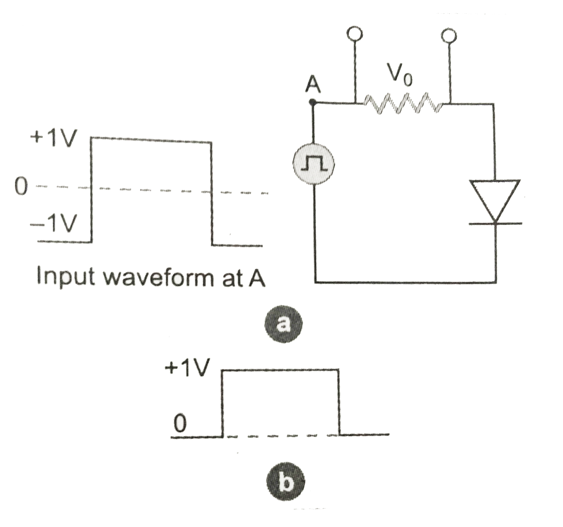
Draw and explain the output waveform across the load resistor R, if the input waveform is as shown in the given.
The output waveforms have been shown in the . It is on account of the fact that a p-n junction diode conducts only when it is in forward bias arrangement but does not conduct in the reverse bias arrangement. During the positive half-cycle of input the p-n junction diode isin forward bias. Hence, a current flows through the resistor R and an output voltage is obtained across it. During the negative half-cycle of input the diode, being in reverse bias, does not allow flow of current and hence output voltage across load resistor is zero.

Topper's Solved these Questions
- SEMICONDUCTOR ELECTRONICS : MATERIALS, DEVICES AND SIMPLE CIRCUITSBOOK - U-LIKE SERIESCHAPTER - SEMICONDUCTOR ELECTRONICS : MATERIALS, DEVICES AND SIMPLE CIRCUITSEXERCISE - LONG ANSWER QUESTIONS-I
22 Videos
- SEMICONDUCTOR ELECTRONICS : MATERIALS, DEVICES AND SIMPLE CIRCUITSBOOK - U-LIKE SERIESCHAPTER - SEMICONDUCTOR ELECTRONICS : MATERIALS, DEVICES AND SIMPLE CIRCUITSEXERCISE - SELF ASSESSMENT TEST (MULTIPE CHOICE QUESTIONS )SECTION A
3 Videos
- SEMICONDUCTOR ELECTRONICS : MATERIALS, DEVICES AND SIMPLE CIRCUITSBOOK - U-LIKE SERIESCHAPTER - SEMICONDUCTOR ELECTRONICS : MATERIALS, DEVICES AND SIMPLE CIRCUITSEXERCISE - VERY SHORT ANSWER QUESTIONS
33 Videos
- RAY OPTICS AND OPTICAL INSTRUMENTSBOOK - U-LIKE SERIESCHAPTER - RAY OPTICS AND OPTICAL INSTRUMENTSEXERCISE - SELF ASSESSMENT TEST (SECTION B)
3 Videos
- WAVE OPTICSBOOK - U-LIKE SERIESCHAPTER - WAVE OPTICSEXERCISE - SELF ASSESSMENT TEST SECTION C (VERY SHORT ANSWER QUESTIONS)
4 Videos
Similar Questions
Draw and explain the output waveform across the load resistor R, if the input wave from is as shown in Fig.

View SolutionDraw the output waveform across the resistor (Fig.)

View SolutionDraw the output waveform across the resistor (Fig.)

View SolutionWhat is an ideal diode ? Draw the output waveform across the load resistor R, If the wavelength is as shown in the figure.
_S01_097_Q01.png)
View SolutionWhat is an ideal diode ? Draw the output waveform across the load resistor R, If the wavelength is as shown in the figure.
_S01_097_Q01.png)
View SolutionThe output waveform of AND gate for the following input waveforms is

View SolutionWrite the output waveform of the OR gate for the inputs
View SolutionShow the output waveform of OR gate for the following input waveforms of A and B

View SolutionShow the output waveform of OR gate for the following input waveforms of A and B

View SolutionShow the output waveform of OR gate for the following input waveforms of A and B

View Solution
