Draw the current-voltage characteristics for the device shown in figure between the terminal A and B.
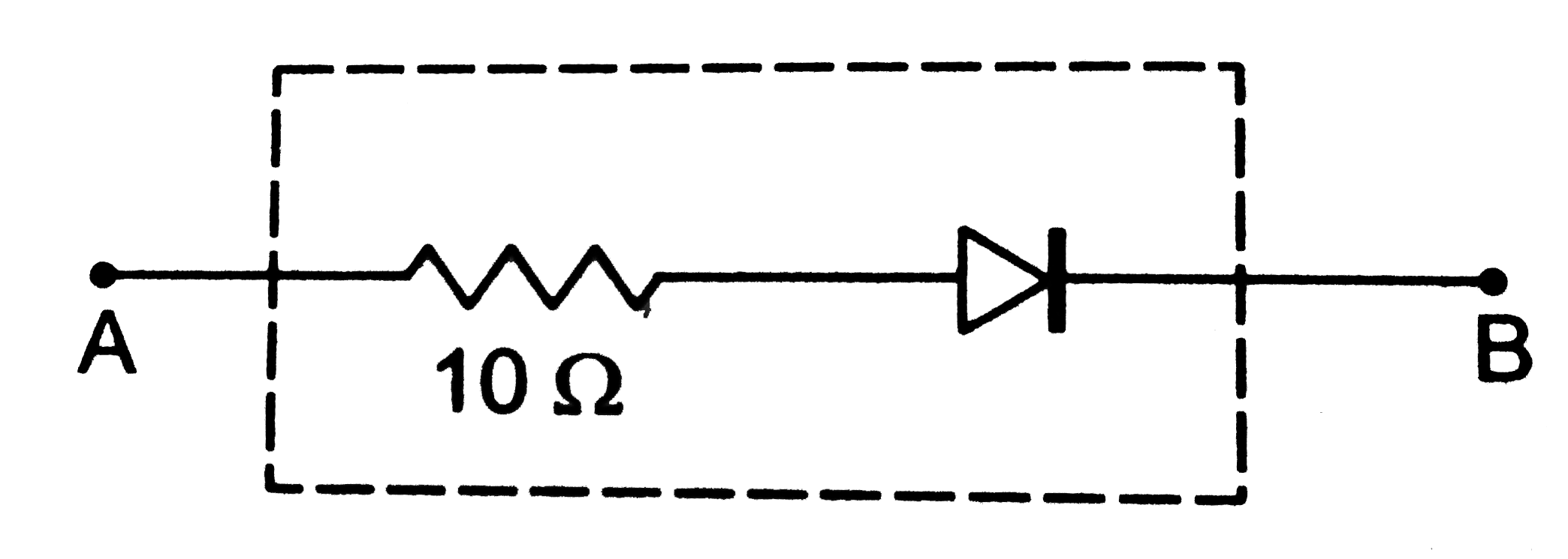

Drow yourself.
Similar Questions
Knowledge Check
The current-voltage graph of a device is shown in figure. The resistance is negative in region.
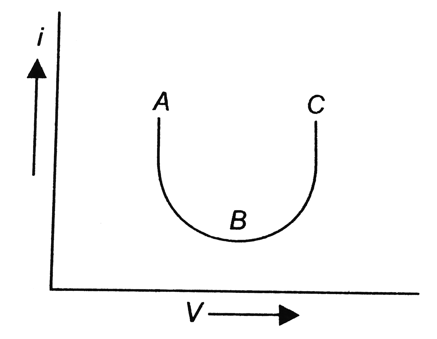 AABBBCCABCDNone of these
1-V characteristics of four devices are shown in figure.
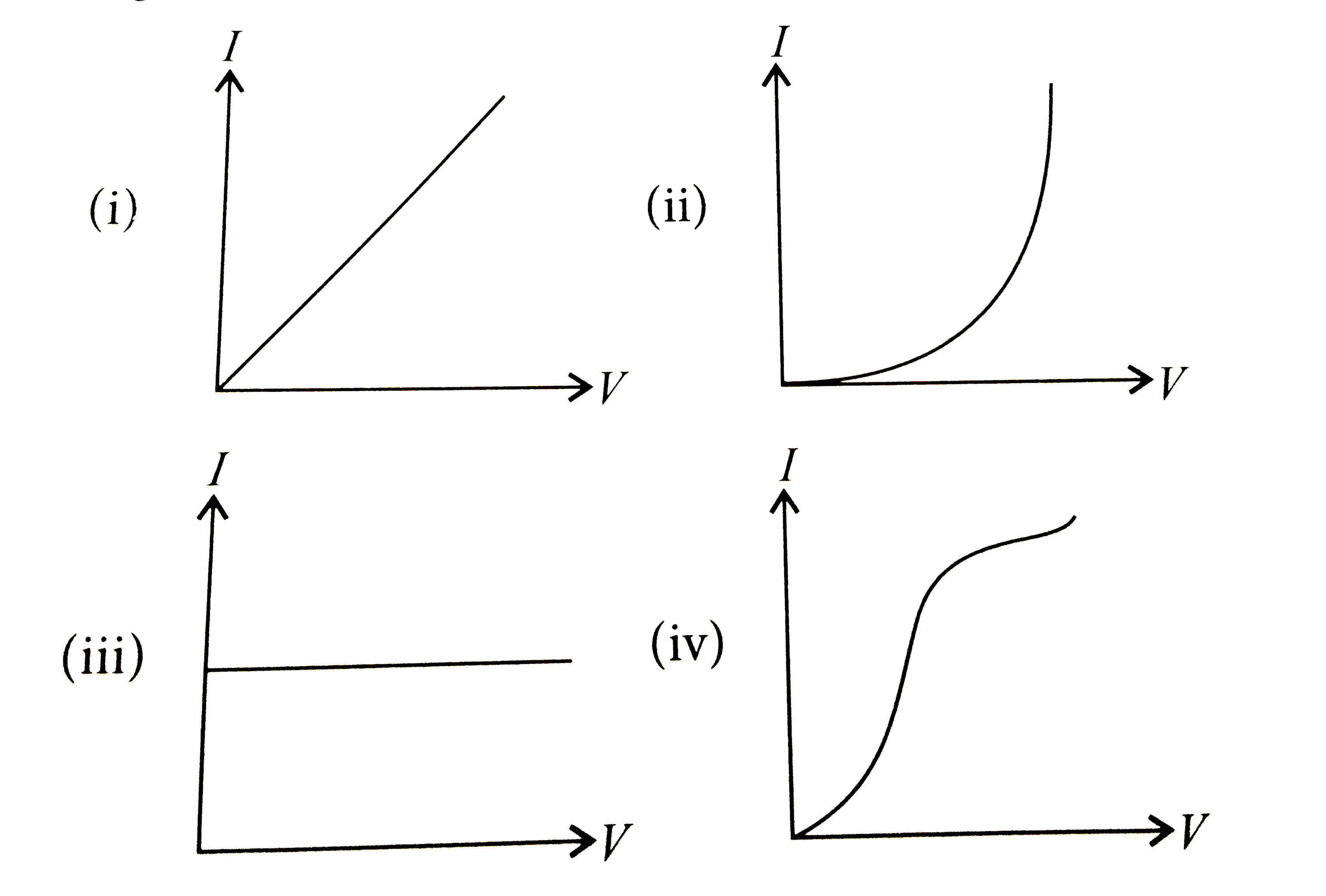
Identify devices that can be used for modulationA(i) and (iii)BOnly (iii)C(ii) and some regions of (iv)DAll the devices can be used
Consider a box with three terminals on top of it as shown in figure.
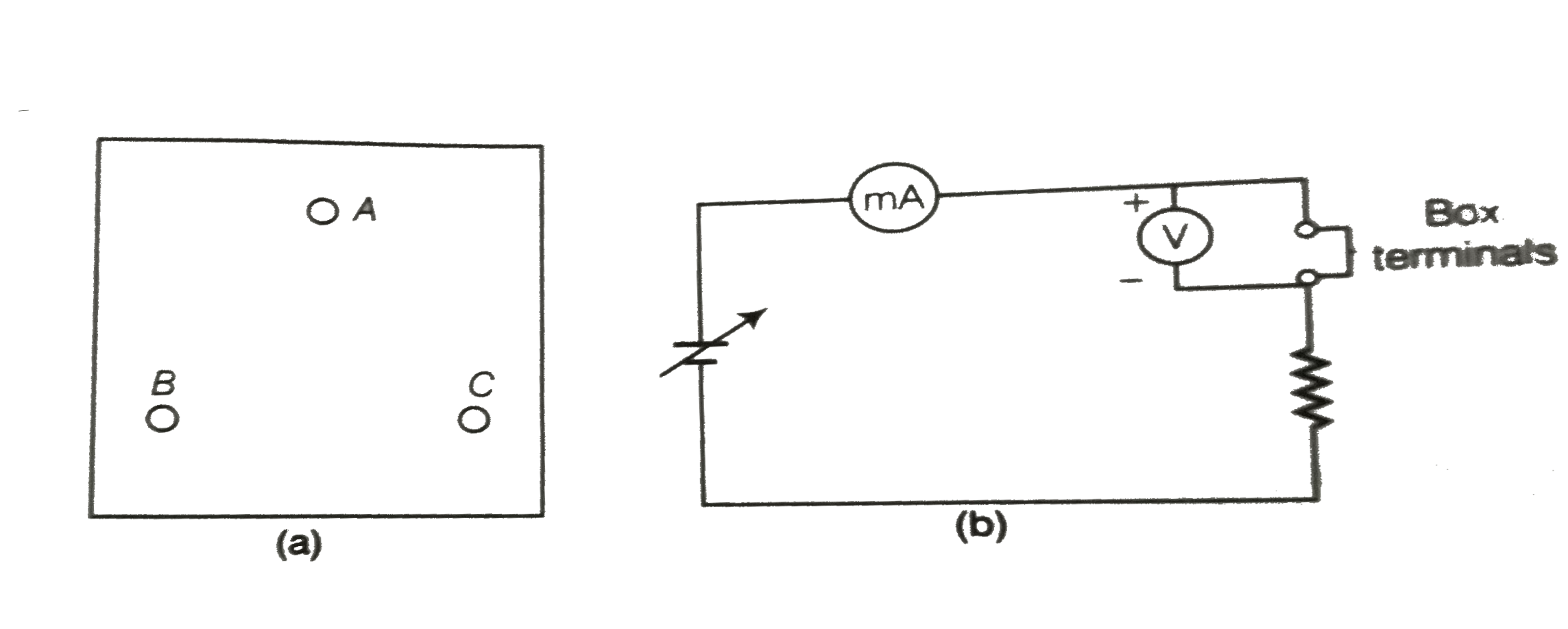
Three components namely, two germanium diodes and one resistor are connected across these three terminals in some arrangement
A student performs an experiment in which any two of these three terminals are connected in the circuit shown in figure.
The student obtains graphs of current-voltage characteristics for unknown combination of components between the two terminals connected in the circuit. The graphs are
(i) When A is positive and B is negative
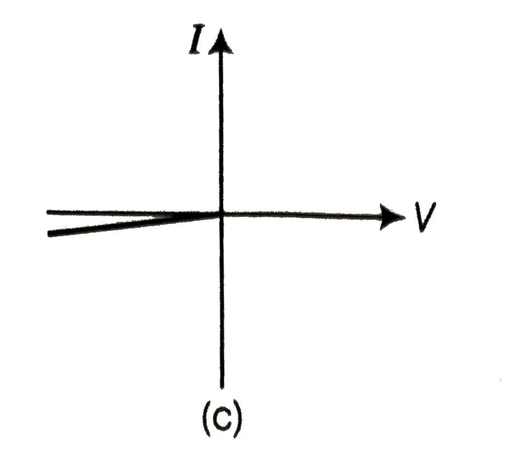
(ii) When A is negative and B is positive
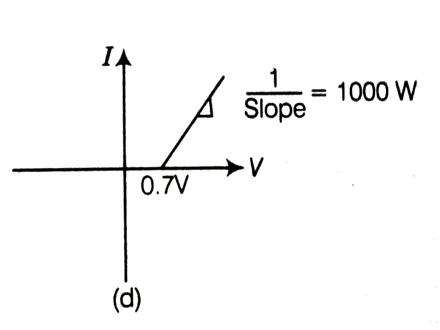
(iii) When B is negative and C is positve
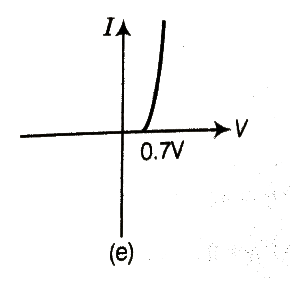
(iv) When B is positive and C is neagtive
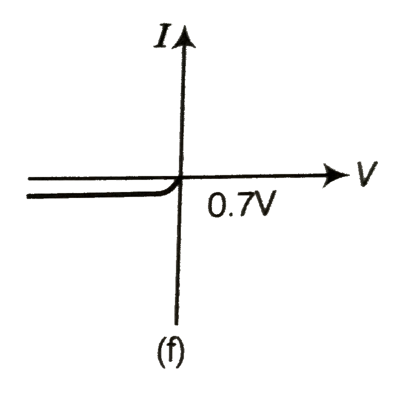
(v) When A is positive and C is negative
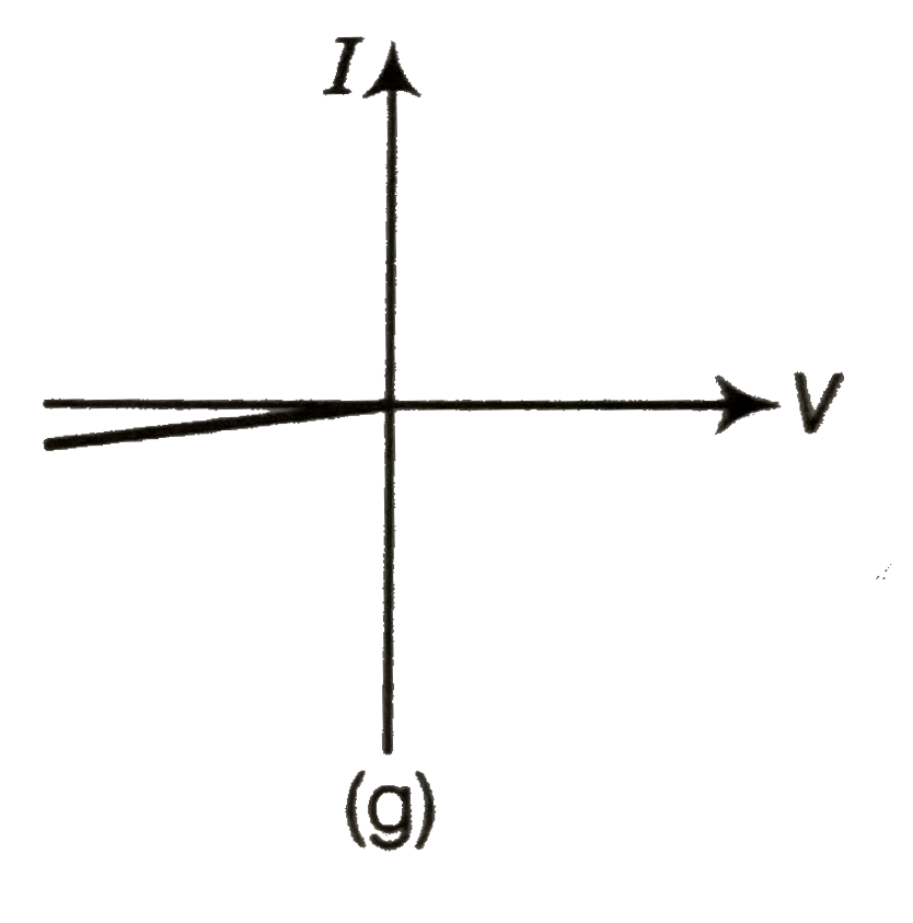
(vi) When A is negative and C is positive
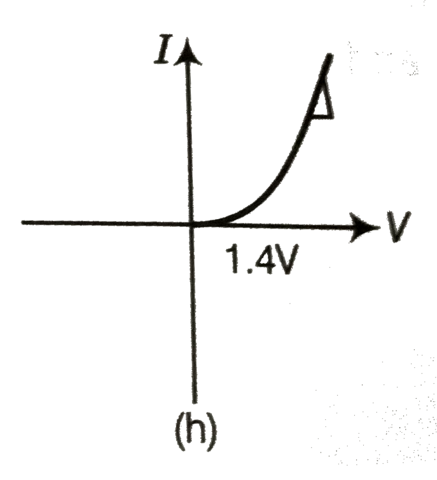
From these graphs of current − voltage characteristic shown in fig. (c) to (h) determine the arrangement of components between A, B and C.
View SolutionConsider a box with three terminals on top of it as shown in figure.

Three components namely, two germanium diodes and one resistor are connected across these three terminals in some arrangement
A student performs an experiment in which any two of these three terminals are connected in the circuit shown in figure.
The student obtains graphs of current-voltage characteristics for unknown combination of components between the two terminals connected in the circuit. The graphs are
(i) When A is positive and B is negative

(ii) When A is negative and B is positive

(iii) When B is negative and C is positve

(iv) When B is positive and C is neagtive

(v) When A is positive and C is negative

(vi) When A is negative and C is positive

From these graphs of current − voltage characteristic shown in fig. (c) to (h) determine the arrangement of components between A, B and C.
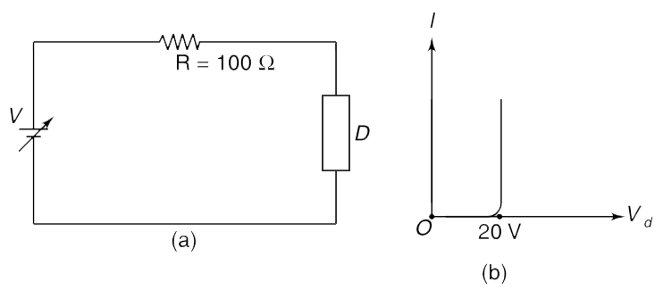
View SolutionThe current – voltage characteristic of an electric device is as shown in figure (b). The device gets damaged if power dissipated in it exceeds 1 Watt. This device is connected to a dc source of variable emf (V) and a resistance (R=100Ω) in series. What is possible range of V for which the device remains operational (i.e. consumes some power) and safe.
View Solution1-V characteristics of four devices are shown in figure.
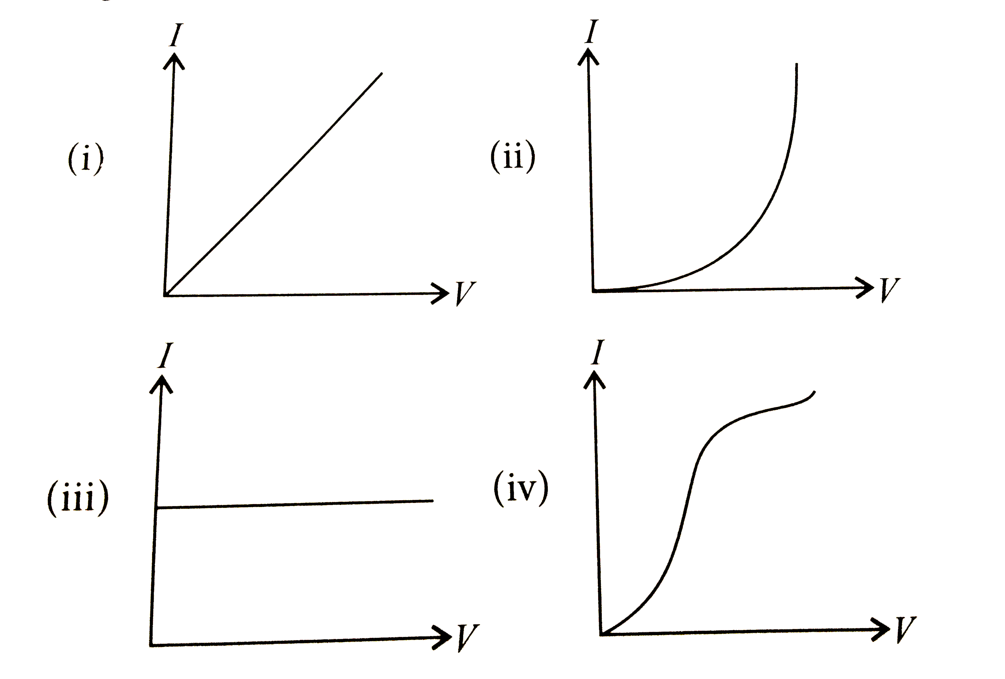
Identify devices that can be used for modulation
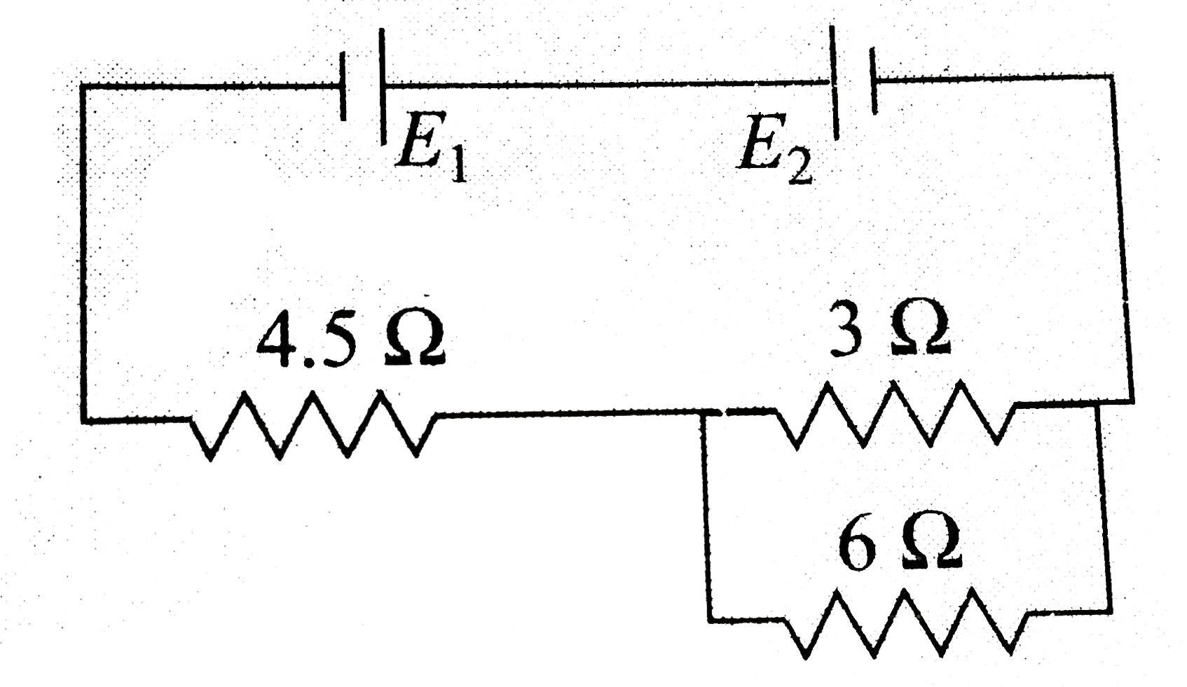
View SolutionCalculate the resistance between the terminals A and B of the network shown in fig
View SolutionThe current (I) – voltage (V) characteristic of three devices A, B and C connected in the circuit is as shown below.
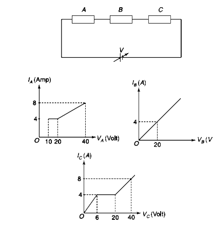
Plot the variation of current through the cell when its emf is changed from 0 and 90 V.
View Solution
