Consider a box with three terminals on top of it as shown in figure.
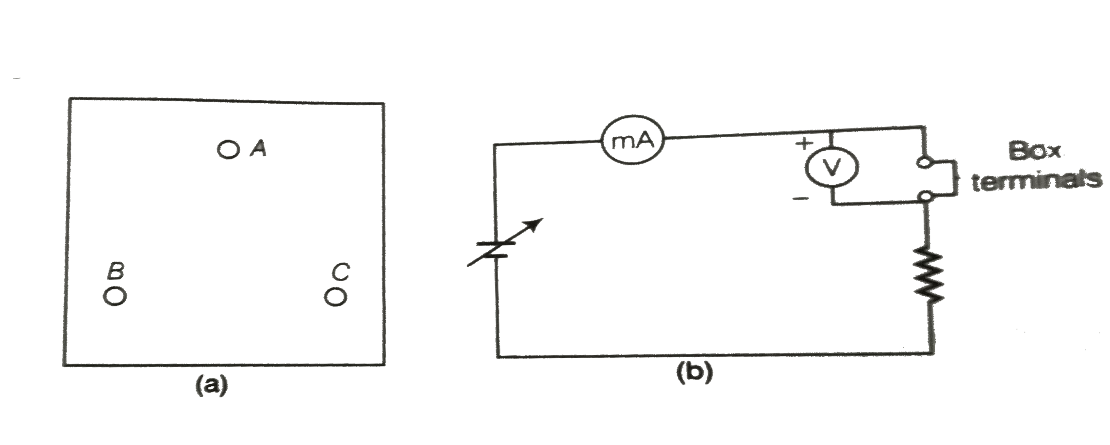
Three components namely, two germanium diodes and one resistor are connected across these three terminals in some arrangement
A student performs an experiment in which any two of these three terminals are connected in the circuit shown in figure.
The student obtains graphs of current-voltage characteristics for unknown combination of components between the two terminals connected in the circuit. The graphs are
(i) When A is positive and B is negative
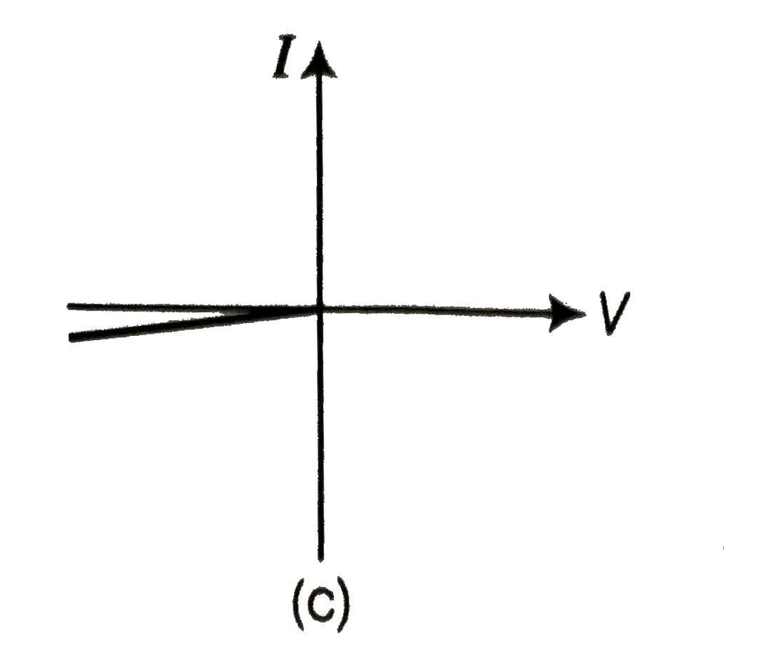
(ii) When A is negative and B is positive
(iii) When B is negative and C is positve
(iv) When B is positive and C is neagtive
(v) When A is positive and C is negative
(vi) When A is negative and C is positive
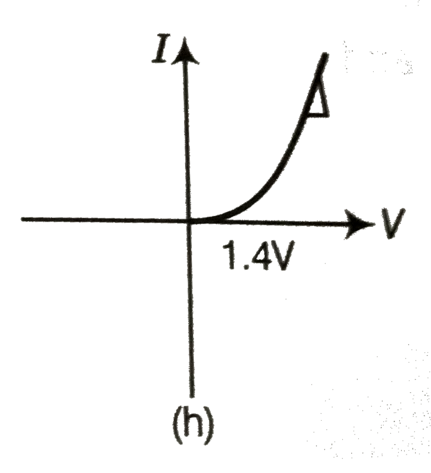
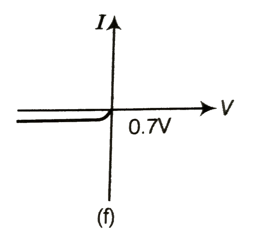
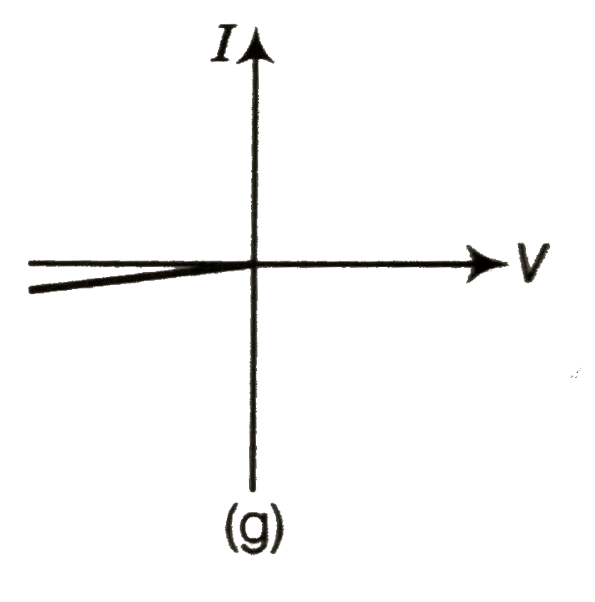
From these graphs of current − voltage characteristic shown in fig. (c) to (h) determine the arrangement of components between A, B and C.
(a) In V−I graph of condition (i), a reverse characteristics is shown in fig. (c). Here A is connected to n−side of p−n junction I and B is connected to p−side of p−n junction I with a resistance in series.
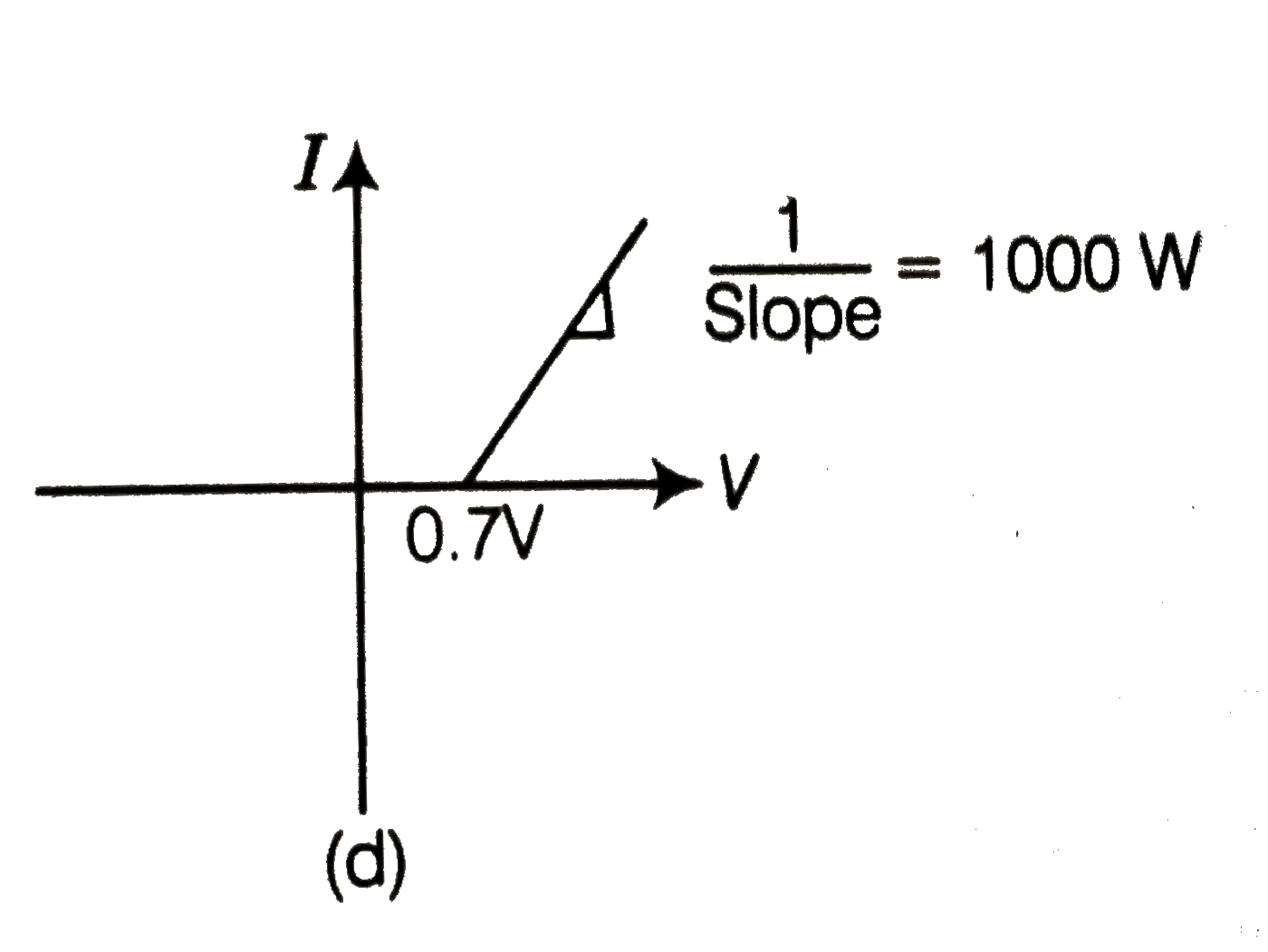
(b) In V−I graph of condition (ii), a forward characteristics is shown in fig. (d), where 0.7V is the knee voltage of p−n junction 11/slope =(1/1000)Ω.
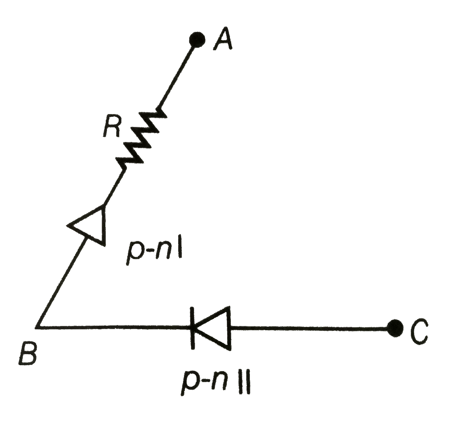
It means A is connected to n− side of p−n junction I and B is connected to p−side of p−n junction I and resistance R is in series of p−n junction I between A and B.
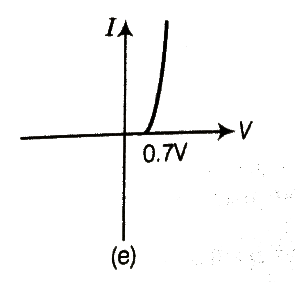
(c) In V=I graph of condition (iii), a forward characteristics is shown in figure (e), where 0.7V is the knee voltage. In this case p−side of p−n junction II is connected to C and n−side of p−n junction II to B.
(d) In V−I graphs of conditions, (iv), (v), (vi) also concludes the above connection of p−n junction I and II along with a resistance R.
Thus, the arrangement of p−nI,p−nII and resistance R between A, B and C will be as shown in the figure.
Topper's Solved these Questions
Similar Questions
Consider a box with three terminals on top of it as shown in figure.

Three components namely, two germanium diodes and one resistor are connected across these three terminals in some arrangement
A student performs an experiment in which any two of these three terminals are connected in the circuit shown in figure.
The student obtains graphs of current-voltage characteristics for unknown combination of components between the two terminals connected in the circuit. The graphs are
(i) When A is positive and B is negative

(ii) When A is negative and B is positive

(iii) When B is negative and C is positve

(iv) When B is positive and C is neagtive

(v) When A is positive and C is negative

(vi) When A is negative and C is positive

From these graphs of current − voltage characteristic shown in fig. (c) to (h) determine the arrangement of components between A, B and C.
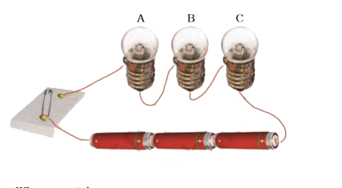
View SolutionThree bulbs A, B, C are connected in a circuit as shown in Figure 14.2. When the switch is ‘ON’
View Solution
Knowledge Check
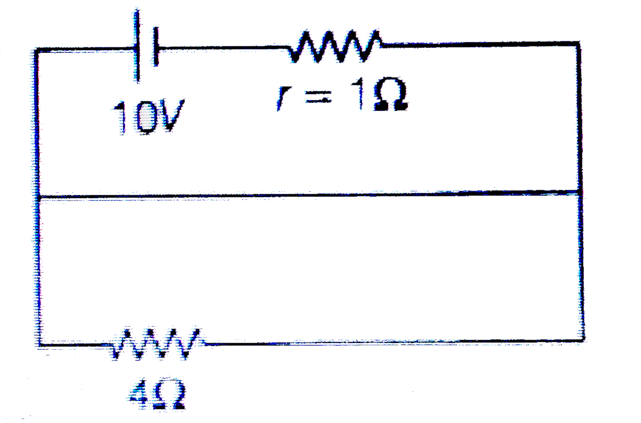
Potential different across the terminals of the battery shown in figure is
 A8 VB10 VC6 VDzero
Three identical bulbs are connected as shown in fig-ure. Choose the correct statement.
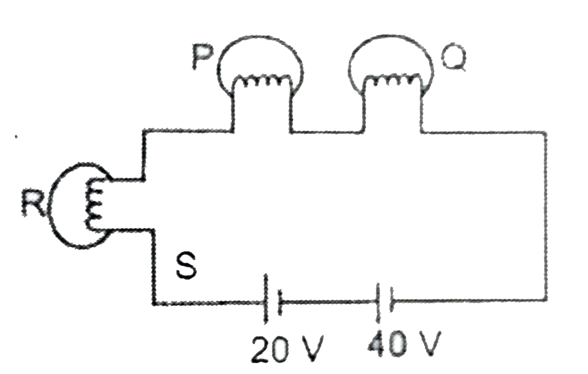 AAll bulbs are in a series combination.BIf bulb R is removed, bulbs P and Q will still glow.CThe total e.m.f in the circuit is 40 V.DThe given circuit is an open circuit.
Three identical bulbs are connected as shown in fig-ure. Choose the correct statement.
 AAll bulbs are in a series combinationBIf bulb R is removed, bulbs P and Q will still glow.CThe total e.m.f in the circuit is 40 V.DThe given circuit is a closed circuit.
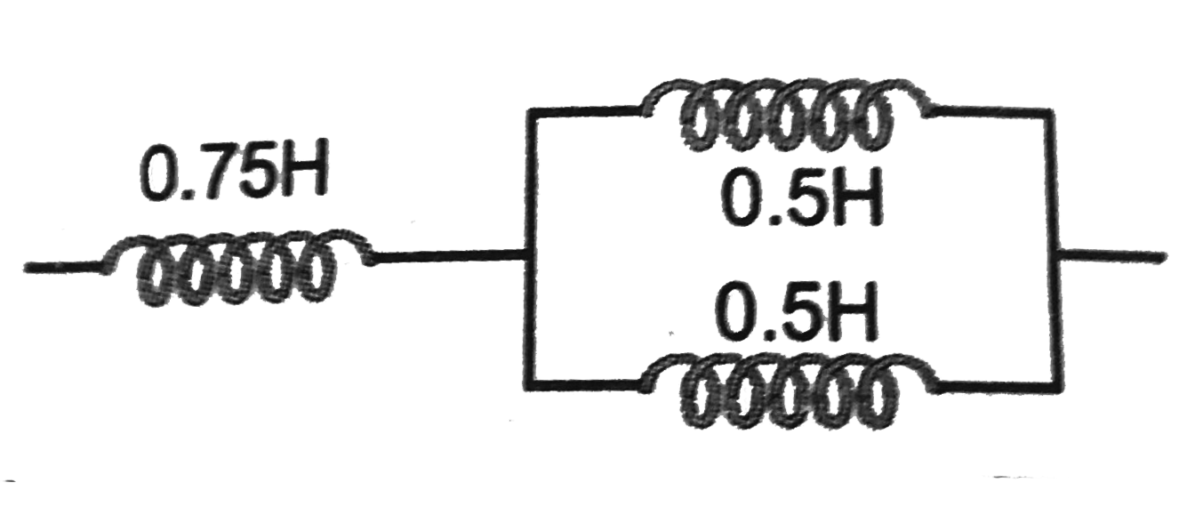
Three inductances are connected as shown in figure. Calculate the resultant inductance.
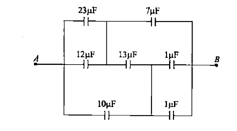
View SolutionFind the equivalent capacitance across terminals A and B in the circuit shown in figure.
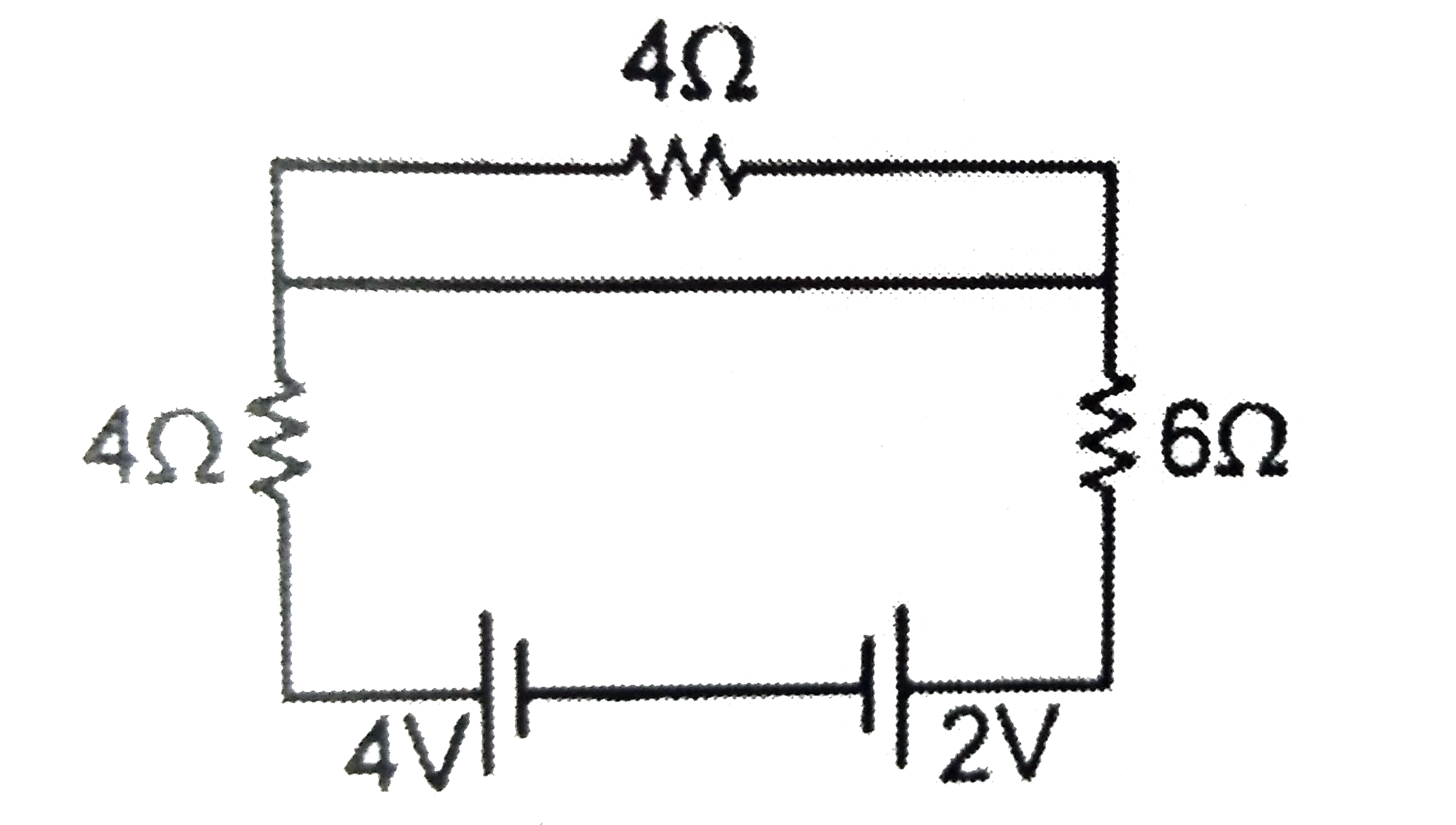
View SolutionFind the currents through the three resistors shown in figure
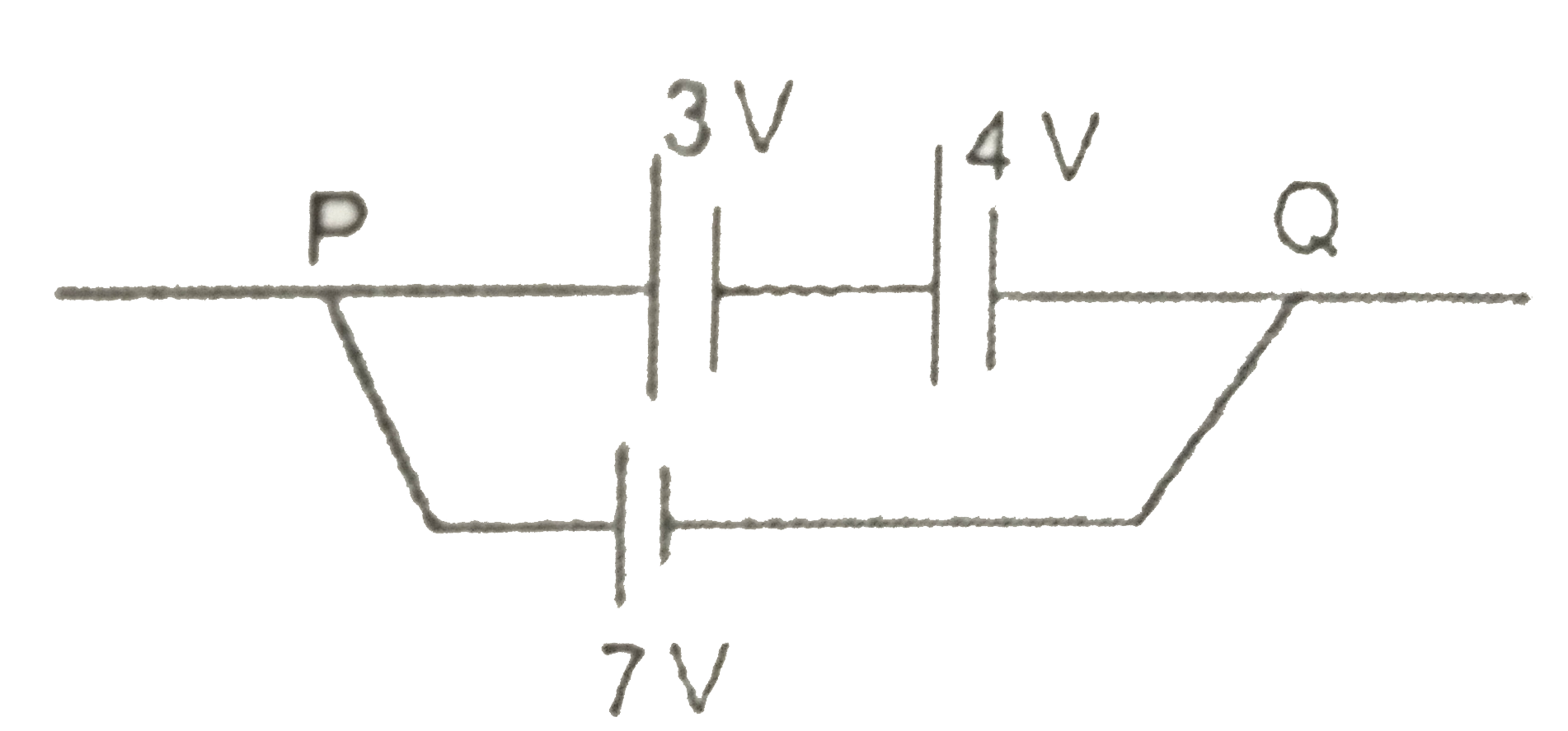
View SolutionThree batteries are connected as shown in the figure.
Then the total emf in the circuit is ____ V.
View SolutionThree batteries are connected as shown in the figure.
Then the total emf in the circuit is ____ V.

View Solution
