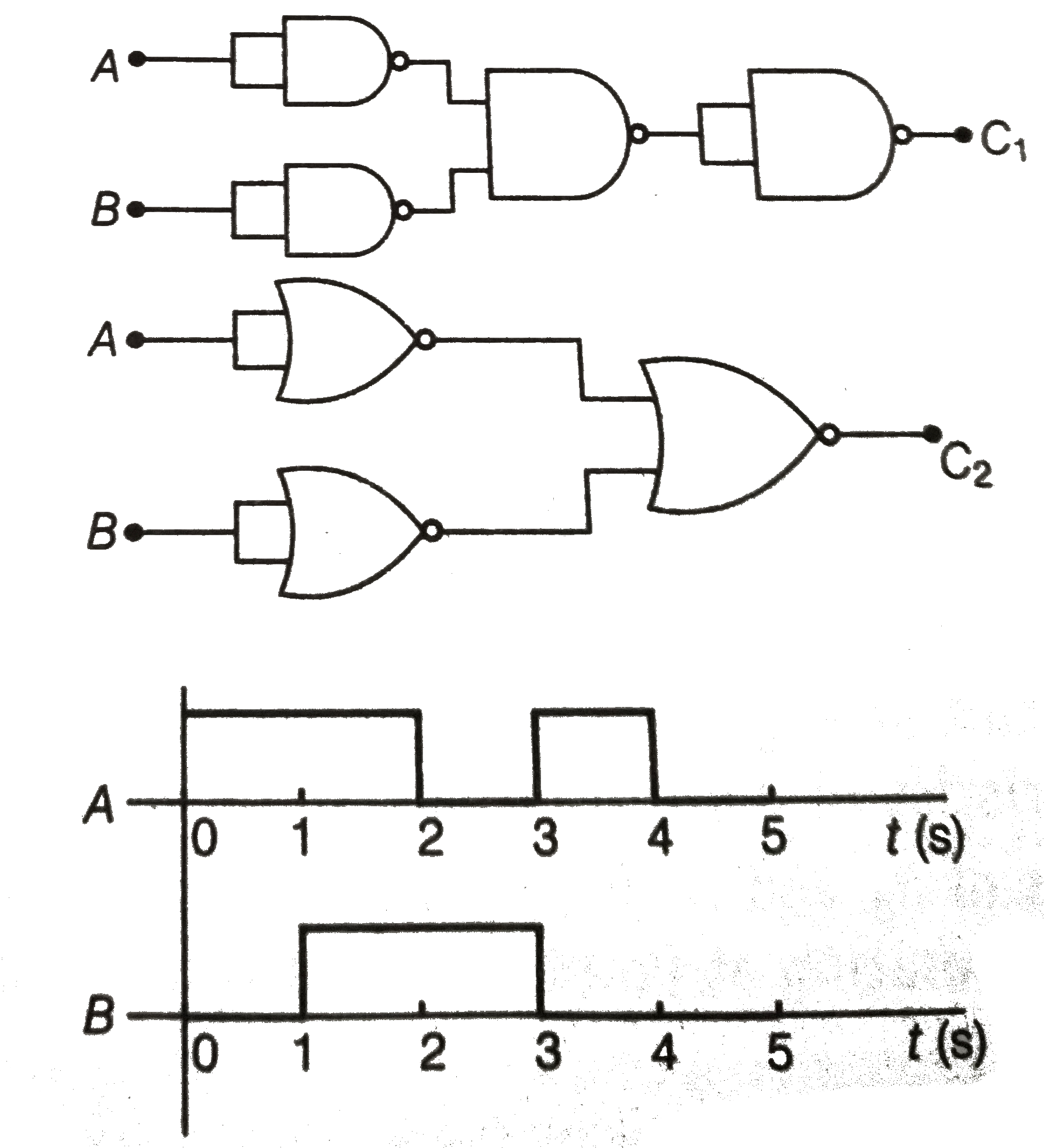
Draw the output signal C1 and C2 in the given combination of gates (Fig.)
Text Solution
Here, In circuit,
C1=¯¯¯¯¯¯¯¯¯¯¯¯¯¯¯¯¯¯¯¯¯A.¯¯¯B=¯¯¯¯¯¯¯¯¯¯¯¯¯¯¯¯¯¯¯¯¯¯¯¯¯baAr+¯¯¯¯¯¯B=¯¯¯¯¯¯¯¯¯¯¯A+B
In circuit,
C2=¯¯¯¯¯¯¯¯¯¯¯¯¯¯¯A+¯¯¯B=4¯¯¯¯¯¯¯A.¯¯¯¯¯¯B=A.B
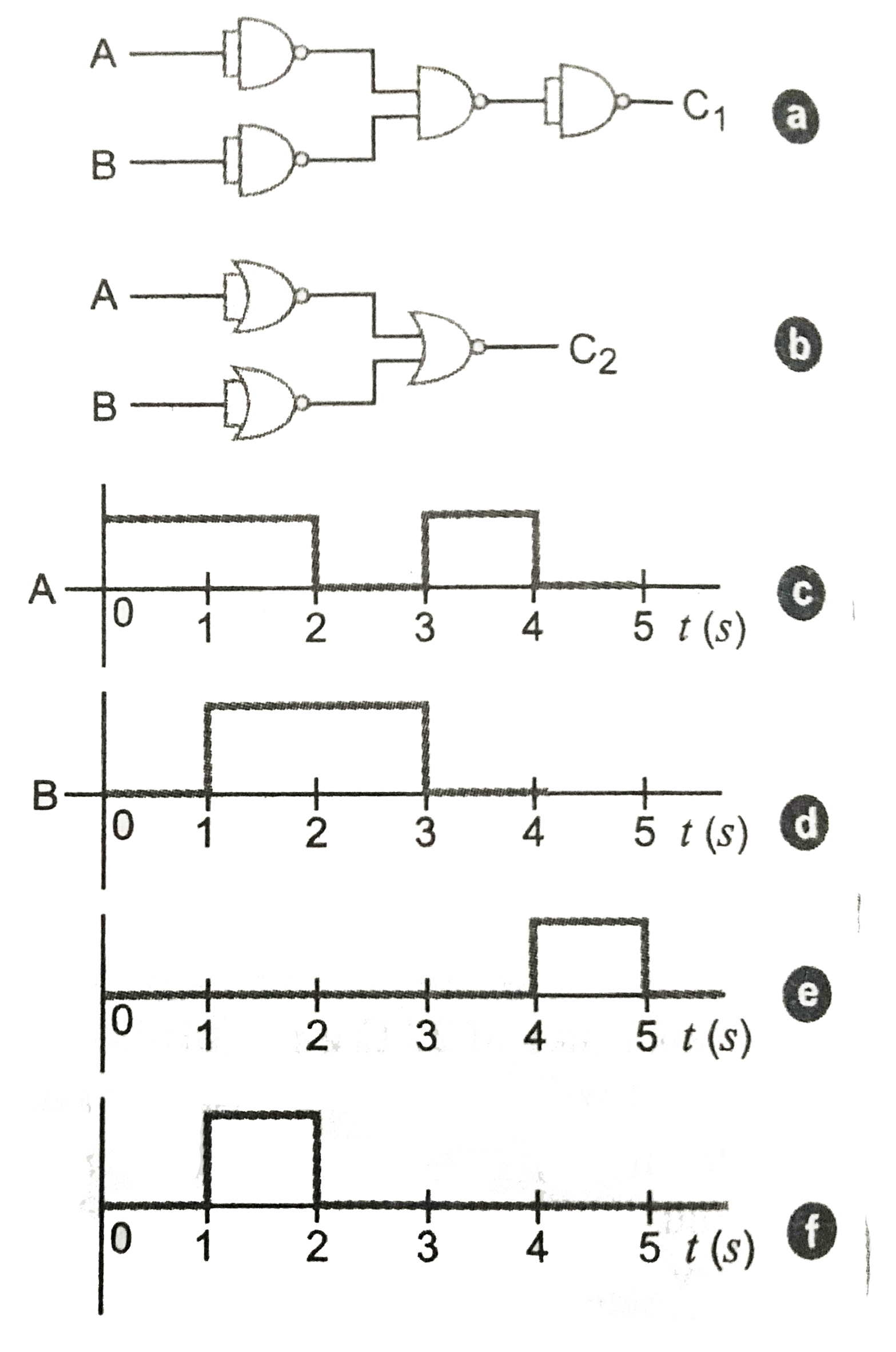
For the given signals shown in Fig. and , we have the following values for A,B,C1 and C2.
(i) For time 0 to 1s,A=1,B=0,C1=0,C2=0
(ii) For time 1s to 2s,A=1,B=1,C1=0,C2=1
(iii) For time 2s→3s,A=0,B=1,C1=0,C2=0
(iv) For time 3s→4s,A=1,B=0,C1=0,C2=0
(v) For time 4s→5s,A=0,B=0,C1=1,C2=0.
The output signal C1 and C2 are shown in Fig.
|
Topper's Solved these Questions
- ELECTRONIC DEVICESBOOK - PRADEEPCHAPTER - ELECTRONIC DEVICESEXERCISE - HIGHER ORDER THINKING SKILLS
1 Videos
- ELECTRONIC DEVICESBOOK - PRADEEPCHAPTER - ELECTRONIC DEVICESEXERCISE - Exercise
312 Videos
- ELECTRONIC DEVICESBOOK - PRADEEPCHAPTER - ELECTRONIC DEVICESEXERCISE - VERY SHORT QUESTION ANSWER (NCERT)
1 Videos
- ELECTROMAGNETIC WAVESBOOK - PRADEEPCHAPTER - ELECTROMAGNETIC WAVESEXERCISE - II Focus multiple choice question
5 Videos
- ELECTROSTATICSBOOK - PRADEEPCHAPTER - ELECTROSTATICSEXERCISE - ASSERTION-REASON TYPE QUESTIONS
2 Videos
Similar Questions
Knowledge Check
_2019_CBT4_E01_066_Q01.png)
The output of the given combination of gates is equivalent to:ANANDBORCANDDNOR
Draw the output signal Y in the given combination of gates :-
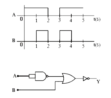
View SolutionIdentify the correct output signal Y in the given combination of gates (as shown) for the given input A and B.
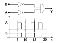
View SolutionIdentify the correct output signal Y in the given combination of gates (as shown) for the given input A and B.

View Solution_2019_CBT4_E01_066_Q01.png)
The output of the given combination of gates is equivalent to:
View SolutionThe output (X) of the given combination of logic gates represents
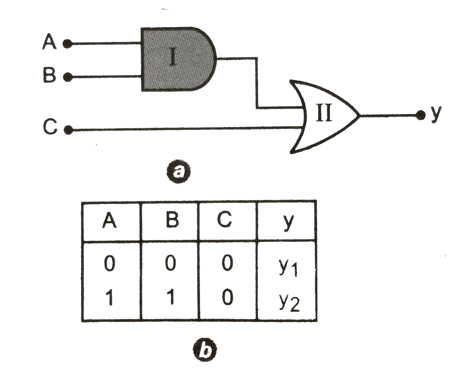
View SolutionFor the given combination of gates shown in Fig., find the values of output y1 and y2 in the table given below Fig. Identify the gates I and II.
View SolutionThe output of the given combination gates represents :

View Solution

