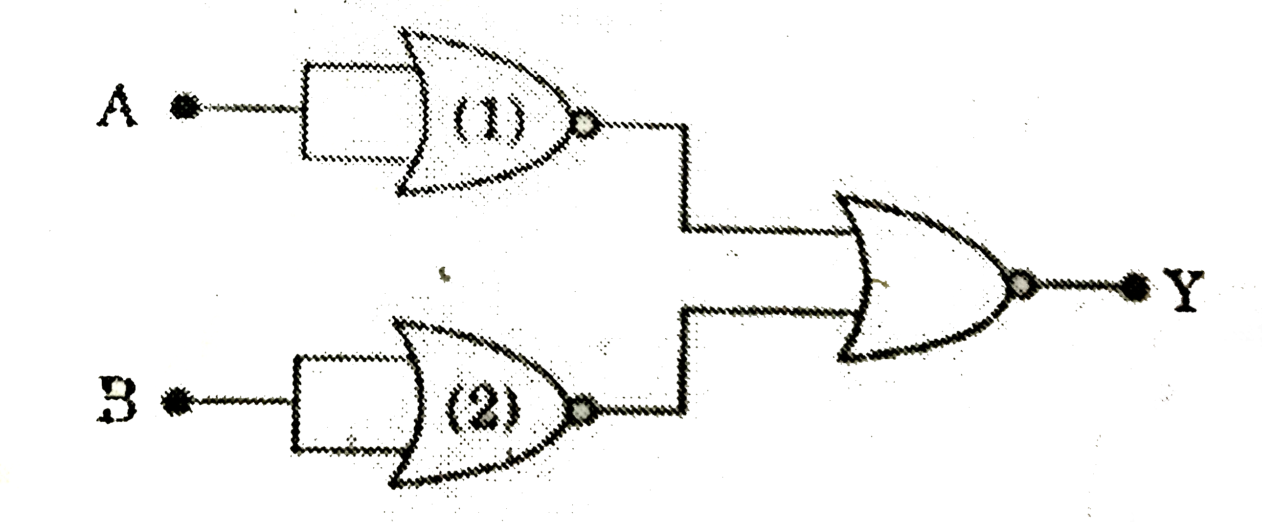
Draw the output signals C1 and C2 in the given combination of gates.
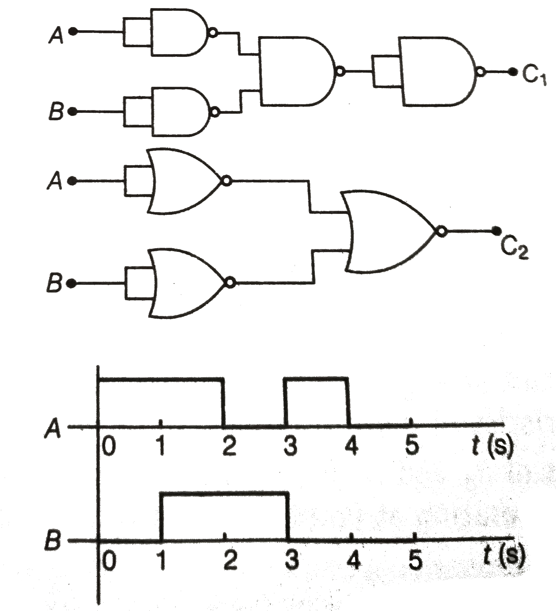
First draw the truth table of C1andC2
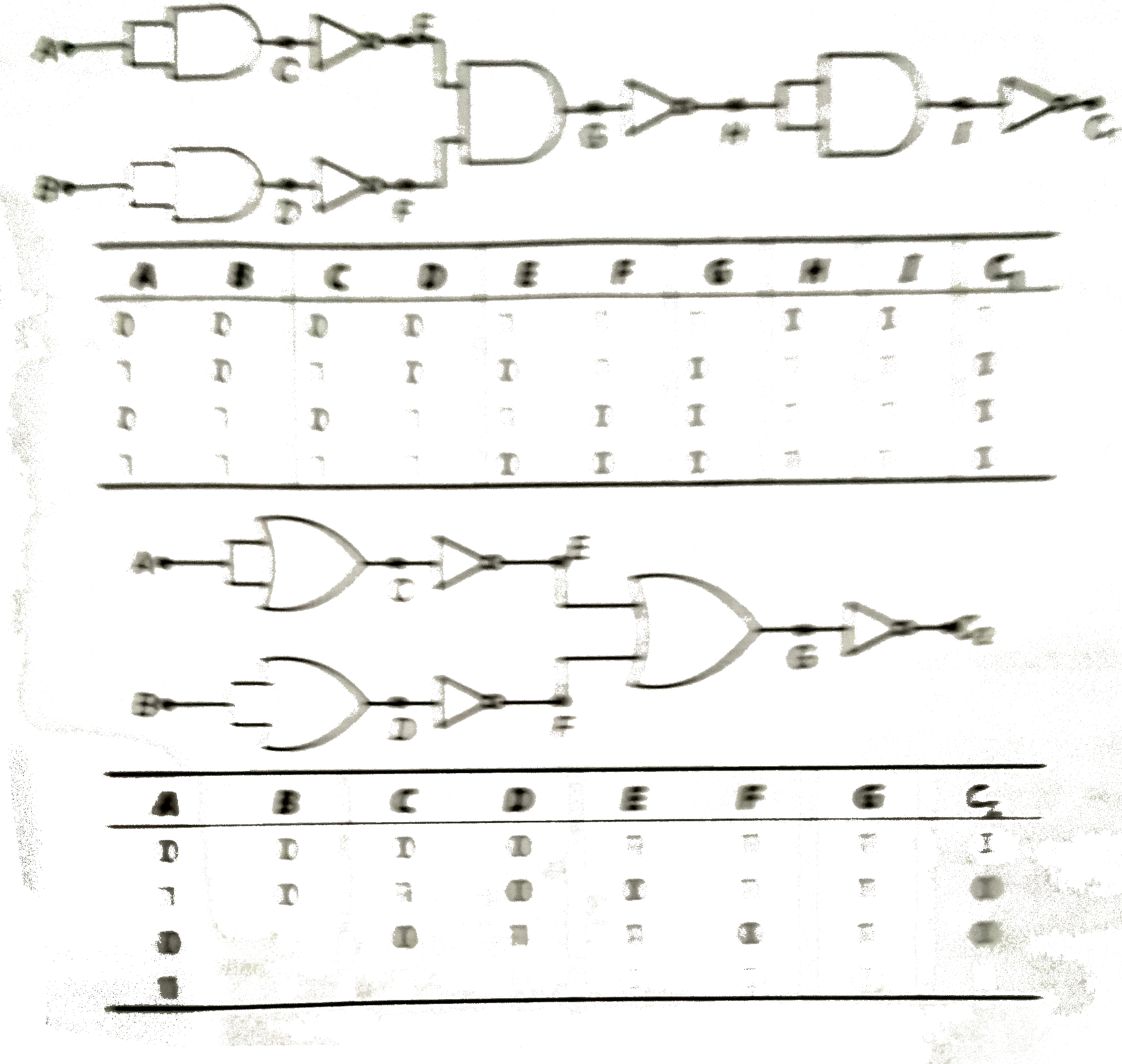
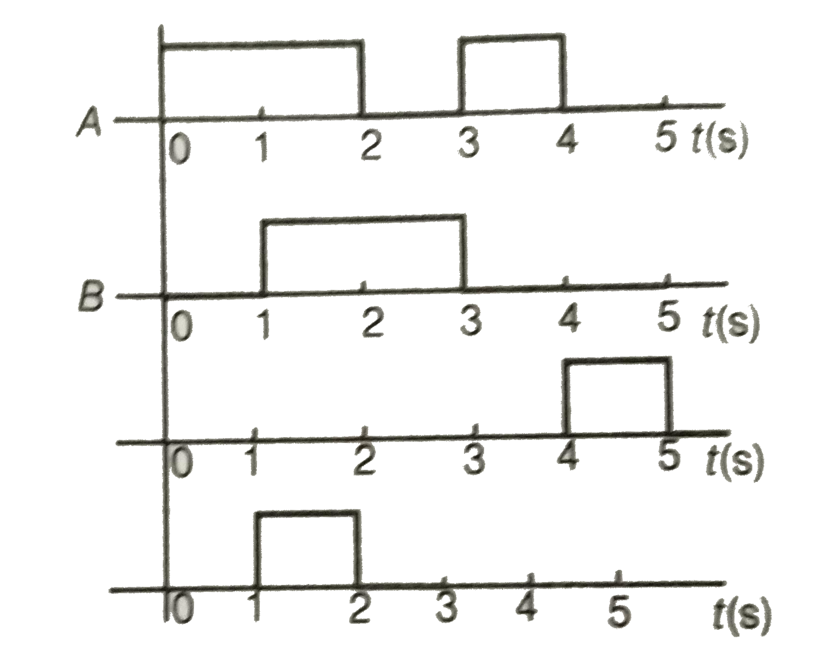
Topper's Solved these Questions
- NUCLEIBOOK - NCERT EXEMPLAR ENGLISHCHAPTER - NUCLEIEXERCISE - Very short Anwer type question
14 Videos
- MOVING CHARNGES AND MAGNETISMBOOK - NCERT EXEMPLAR ENGLISHCHAPTER - MOVING CHARNGES AND MAGNETISMEXERCISE - Long Answer Type Questions
7 Videos
- RAY OPTICS AND OPTICAL INSTRUMENTS BOOK - NCERT EXEMPLAR ENGLISHCHAPTER - RAY OPTICS AND OPTICAL INSTRUMENTS EXERCISE - VERY SHORT ANSWER TYPE QUESTIONS
16 Videos
Similar Questions
Identify the correct output signal Y in the given combination of gates (as shown) for the given input A and B.
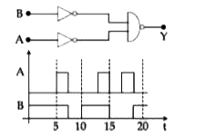
View Solution_2019_CBT4_E01_066_Q01.png)
The output of the given combination of gates is equivalent to:
View SolutionThe output of OR gate is 1
View SolutionThe output of OR gate is 1
View SolutionThe output of the given logica gate is

View SolutionThe output of the given logic gate is

View SolutionThe inputs A and B are inverted by using two NOT gates and their outputs are fed to the NOR gate as shown:
Analyse the action of the gates (1) and (2) and identify the logic gate of the complete circuit so obtained. Give its symbol and the truth table.
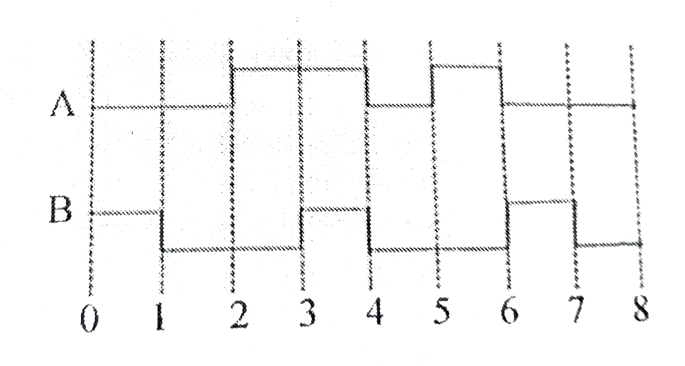
View SolutionDraw the output wave from (Y) of the
(i) OR gate
(ii) NOR gate
(iii) AND gate (iv) NAND gate
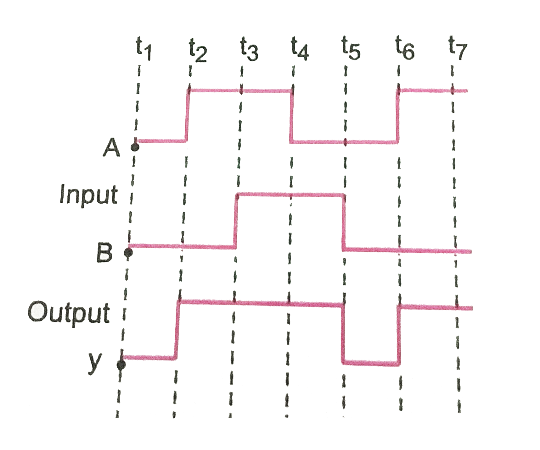
View SolutionThe Fig shown input waveforms A and B to a logic gate. Draw the output waveform for an OR gate. Write the truth table for this logic gate and draw its logic symbol.
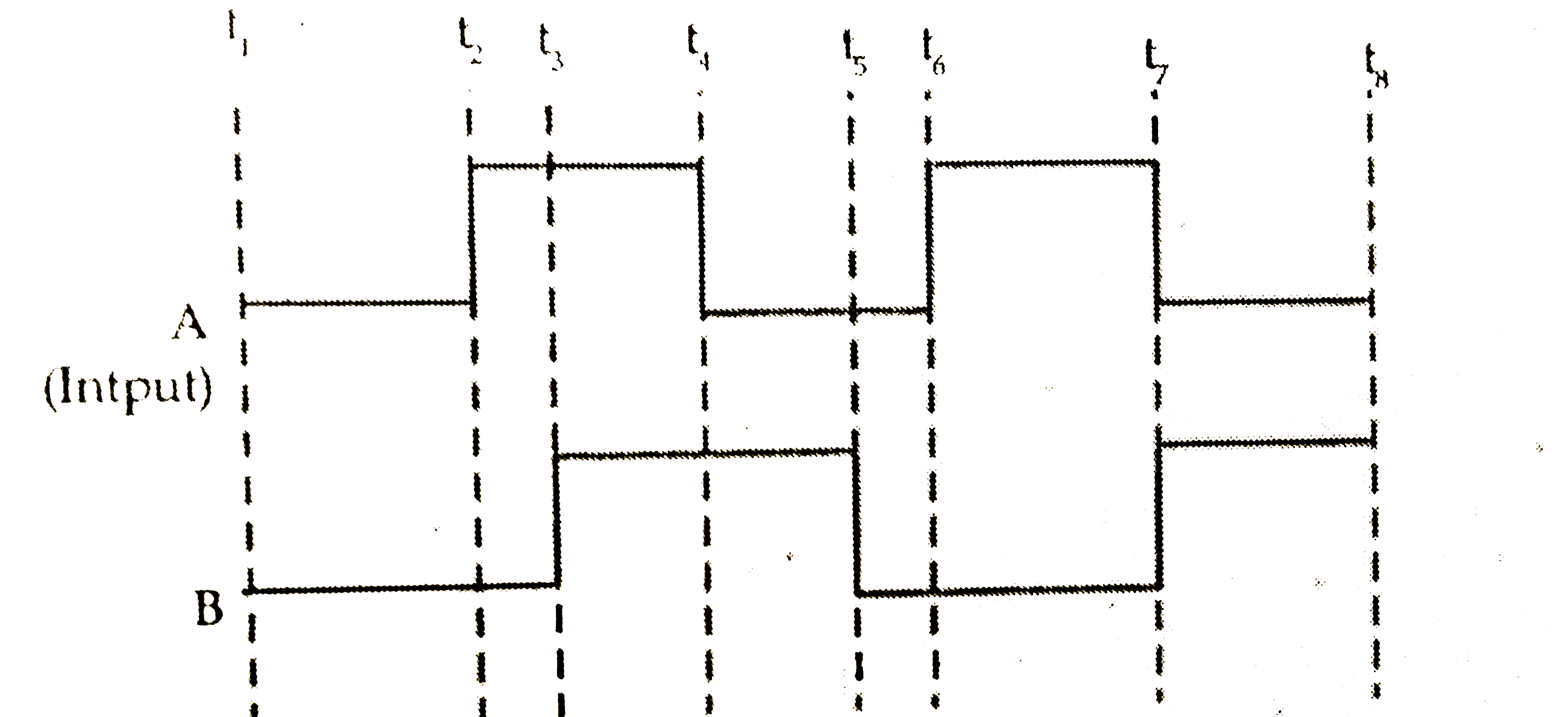
View SolutionThe figure shows the input weveforms A and B for 'AND' gate Draw the output waveform and write the truth table for this logic gate
 .
.
View Solution
