Draw the output waveform across the resistor (Fig.)
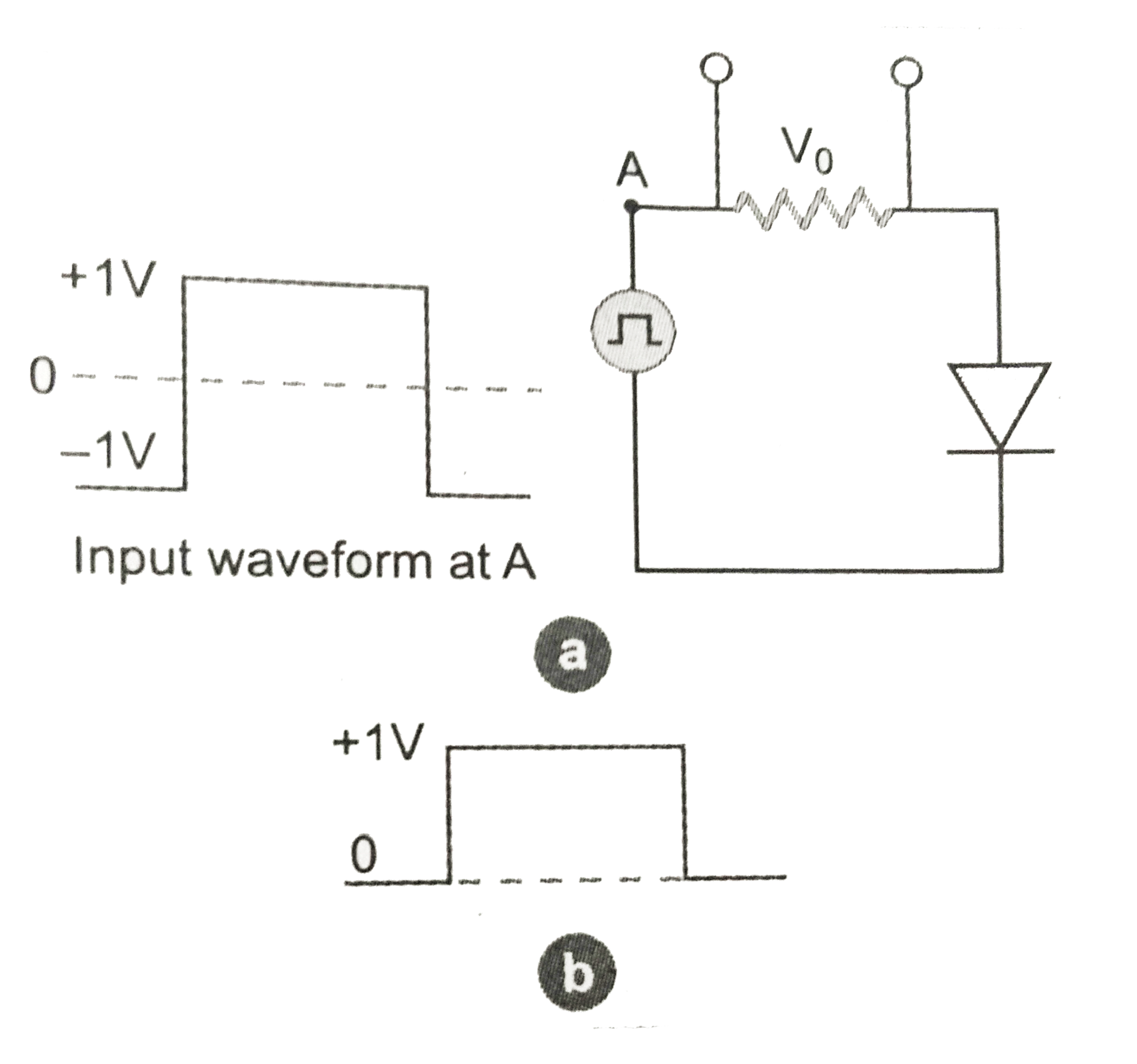
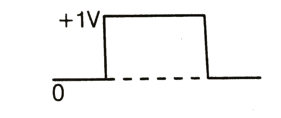
As we know that the diode only works in forward biased, so the output is obtained only when positive input is given, so the output waveform is
Topper's Solved these Questions
- NUCLEIBOOK - NCERT EXEMPLAR ENGLISHCHAPTER - NUCLEIEXERCISE - Long answer type question
10 Videos
- NUCLEIBOOK - NCERT EXEMPLAR ENGLISHCHAPTER - NUCLEIEXERCISE - Long answer type question
10 Videos
- MOVING CHARNGES AND MAGNETISMBOOK - NCERT EXEMPLAR ENGLISHCHAPTER - MOVING CHARNGES AND MAGNETISMEXERCISE - Long Answer Type Questions
7 Videos
- RAY OPTICS AND OPTICAL INSTRUMENTS BOOK - NCERT EXEMPLAR ENGLISHCHAPTER - RAY OPTICS AND OPTICAL INSTRUMENTS EXERCISE - VERY SHORT ANSWER TYPE QUESTIONS
16 Videos
Similar Questions
What is an ideal diode ? Draw the output waveform across the load resistor R, If the wavelength is as shown in the figure.
_S01_097_Q01.png)
View SolutionA square wave (-1 to +1V) is applied to a P-N junction diode as shown. Draw the output wave form across the diode which is assumed to be ideal-
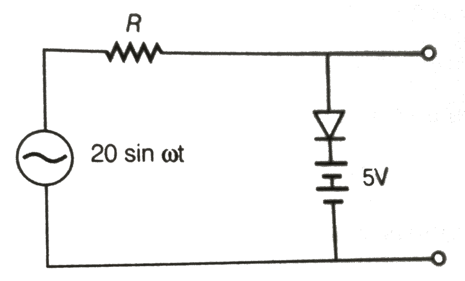
View SolutionAssuming the ideal diode, draw the output waveform for the circuit given in fig. (a), explain the waveform
View Solution

(a) Draw the circuit diagram of reversed bias p-n junction.
(b). Draw the output wavefrom across diode in given circuit.
(c). Draw the truth table for the given logic gate.
View SolutionThe figure shows the input weveforms A and B for 'AND' gate Draw the output waveform and write the truth table for this logic gate
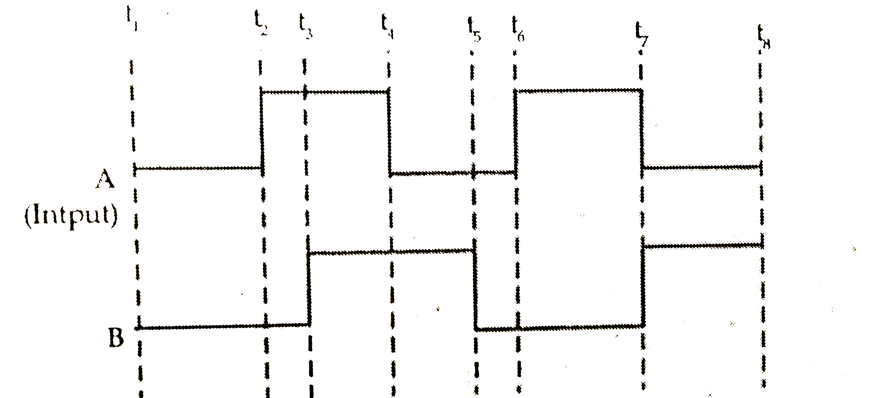 .
.
View SolutionDraw the output waveform X, using the given inputs A and B for the logic circuit shows below. Also, identify the logic operation performed by this circuit.

View SolutionThe Fig shown input waveforms A and B to a logic gate. Draw the output waveform for an OR gate. Write the truth table for this logic gate and draw its logic symbol.
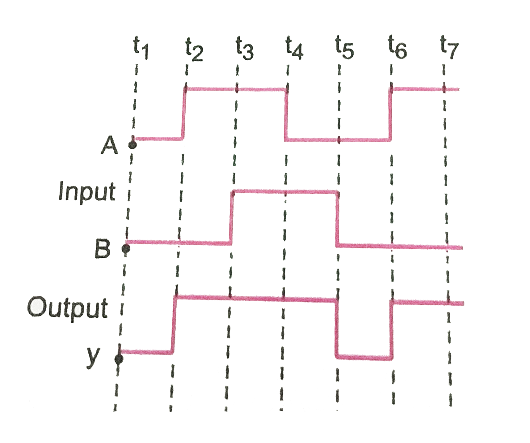
View SolutionDraw the output waveformed at X, using the given inputs A and B for the logic circuit shows below. Also, identify the logic operation performed by this circuit.

View SolutionUsing the wave forms of the input A and B, draw the output waveform of the given logic circuit . Identify the logic gate obtained . Write also the truth table.

View SolutionWhen a battery connected across a resistor of 16Ω, the voltage across the resistor is 12 V. When the same battery is connected across a resistor of 10Ω, voltage across it is 11 V. The internal resistance of the battery (in ohm) is
View Solution
