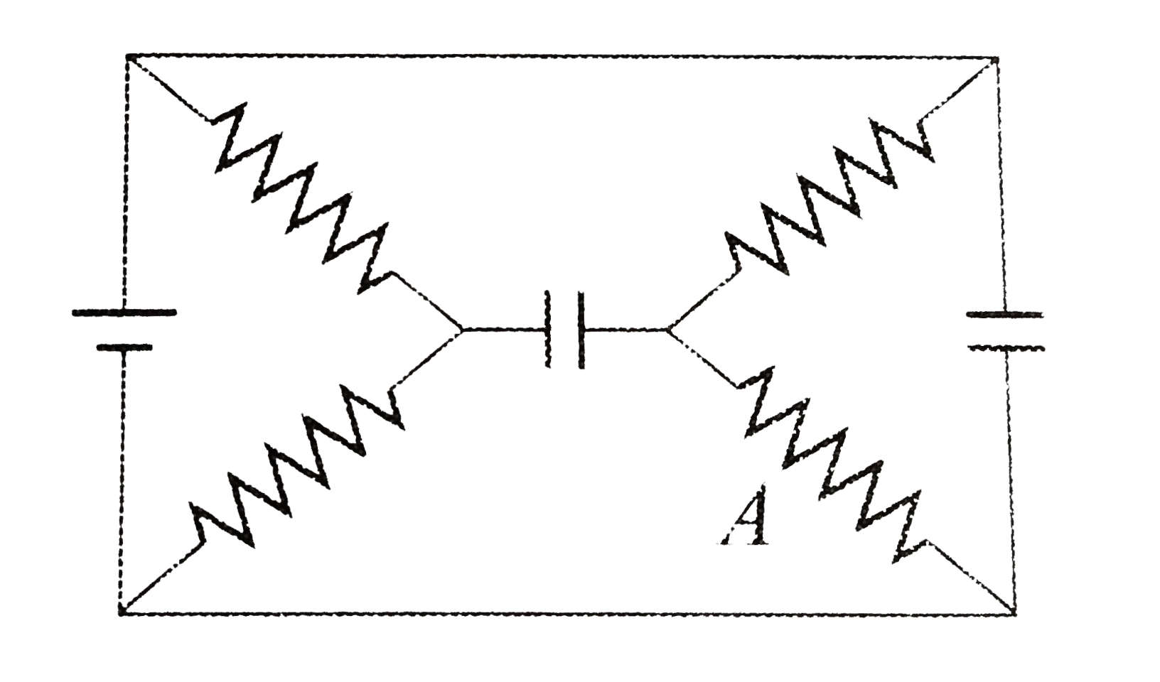
Each resistor in the following circuit has a resistance of 2MΩ and the capacitors have capacitances of 1μF. The battery voltage is 3V. The voltage across the resistor A in the following circuit in steady state is
0 V
0.5 V
0.75 V
1.5 V
The correct Answer is:D
d. This is a dc circuit because the battery is the only source of voltage.
Hence, the capacitors behave like
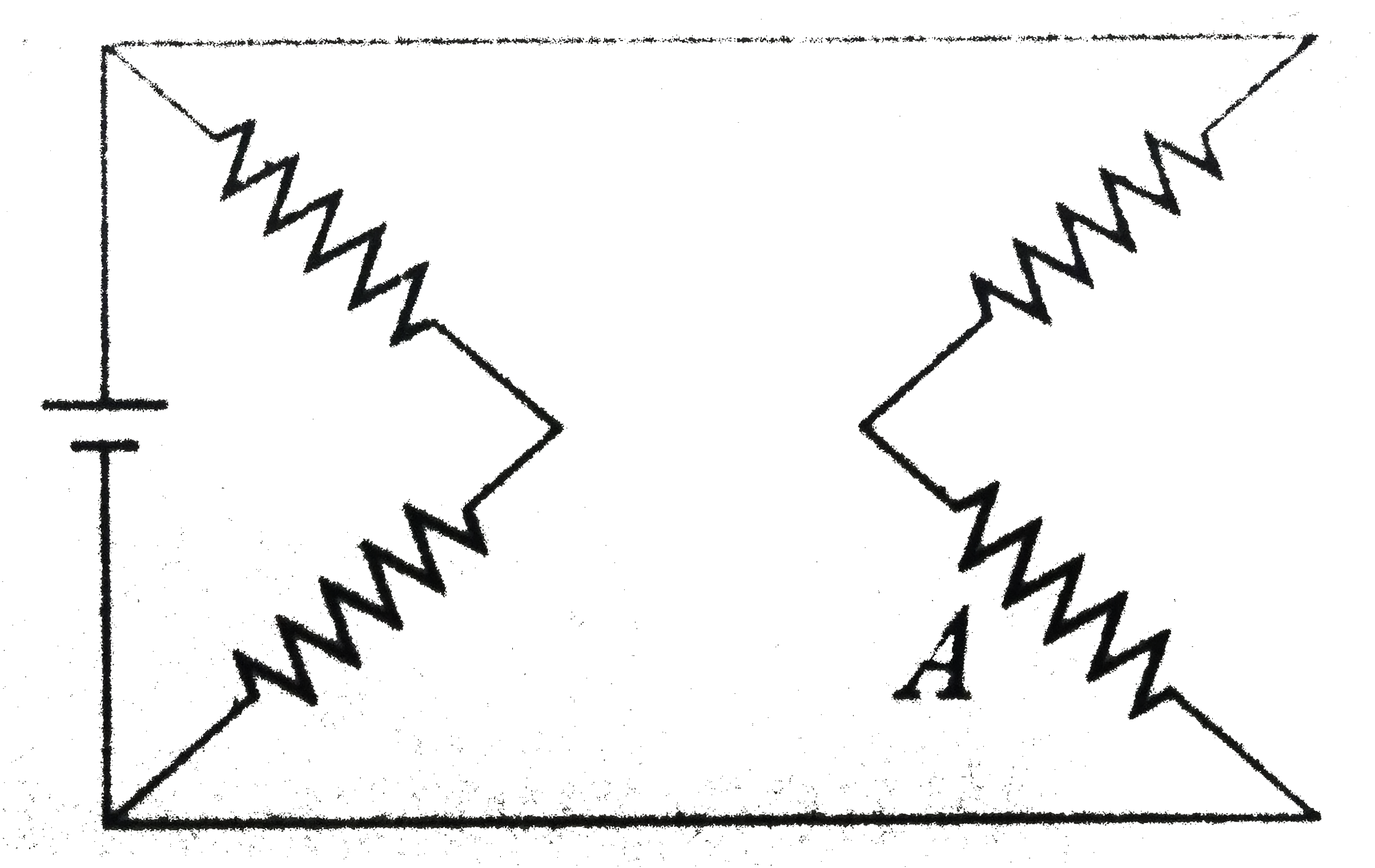
open circuits. An equivalent circuit
is then two parallel sets of two
identical series resistors.
The voltage drop across
each parallel brabch must be the battery voltage of 3V.
Since the resistors are identical, there is an equal voltage
drop of 1.5 V across each resistor. In particular, there is a
drop of 1.5 V across resistor A.
Similar Questions
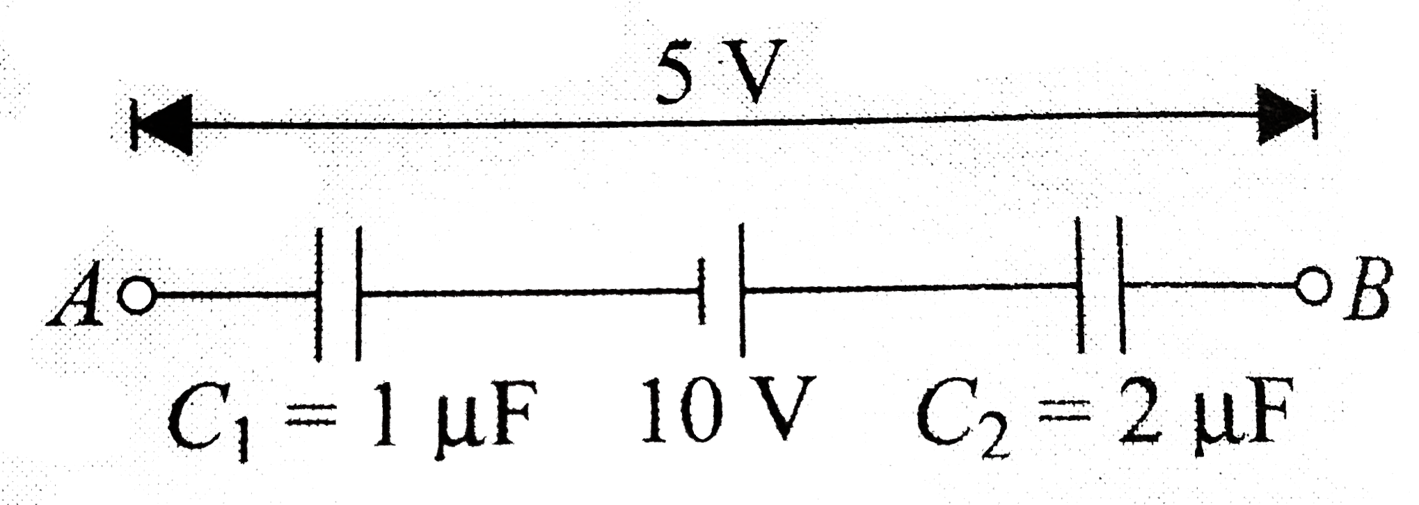
A circuit has section AB as shown in The emf of the cell is 10V, and the capacitors have capacitances C1=1μF and C2=2μF. Find the voltage across each capacitor.
 .View Solution
The charge on the capacitor of capacitance 10μF in steady state condition in the circuit shown is
_PHY_E05_271_Q01.png) View Solution
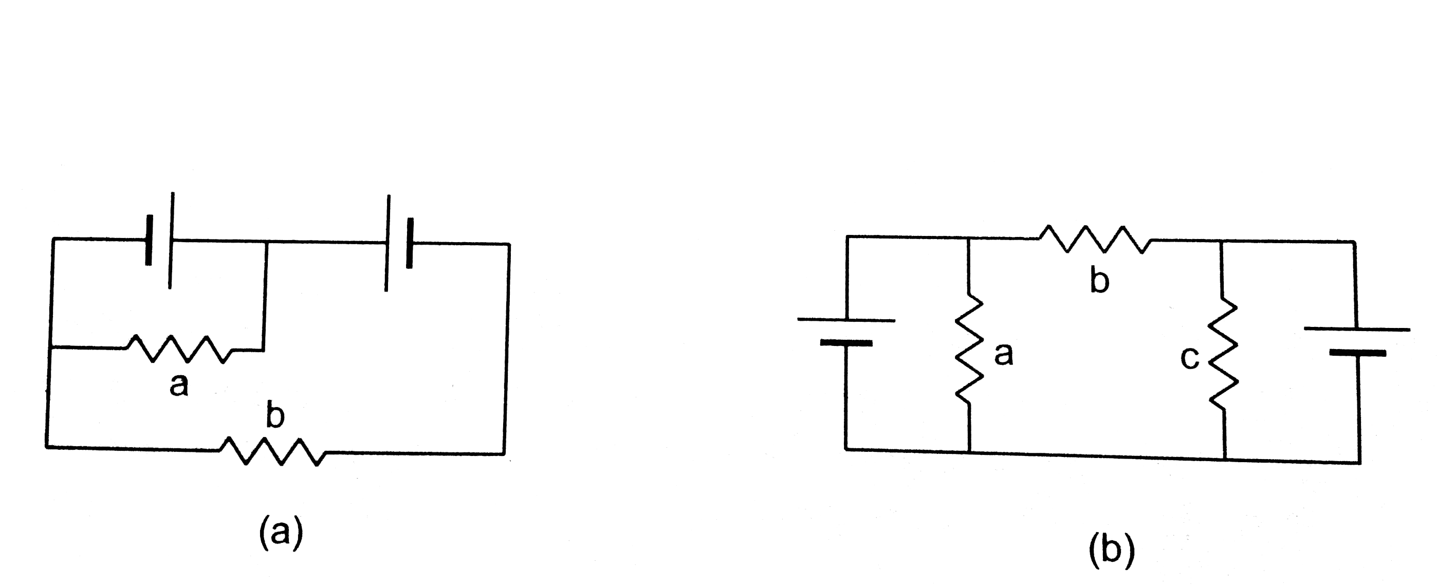
View SolutionEach of the resistors shown in figure has a resistances of 10(Ω)and each of the batteries has an emf of 10V.Find the currents through the resistors a and b in the two circuits.
 View Solution
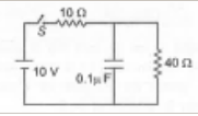
Two resistors of resistances 10Ω and 40Ω are connected with a capacitor of capacitance 0.1μF and ideal battery of emf 10 V. When switch (S) is closed, then initial current and current in steady state through the battery respectively are
 View Solution
Three resistors having resistances of 1.60Ω,2.40Ω and 4.80Ω are connected in parallel to a 28.0V battery that has negligible internal resistance. Find
(a) the equivalent resistance of the combination.
(b) the current in each resistor.
(c) the total current through the battery.
(d) the voltage across each resistor.
(e) the power dissipated in each resistor.
(f) which resistor dissipates the maximum power the one with the greatest resistance or the least resistance? Explain why this should be.View SolutionThe circuit consists of two resistors (of resistance R1=20Ω and R2=10Ω), a capacitor (of capacitance C=10μF) and two ideal cells. In the circuit shown the capacitor is in steady state and the switch S is open
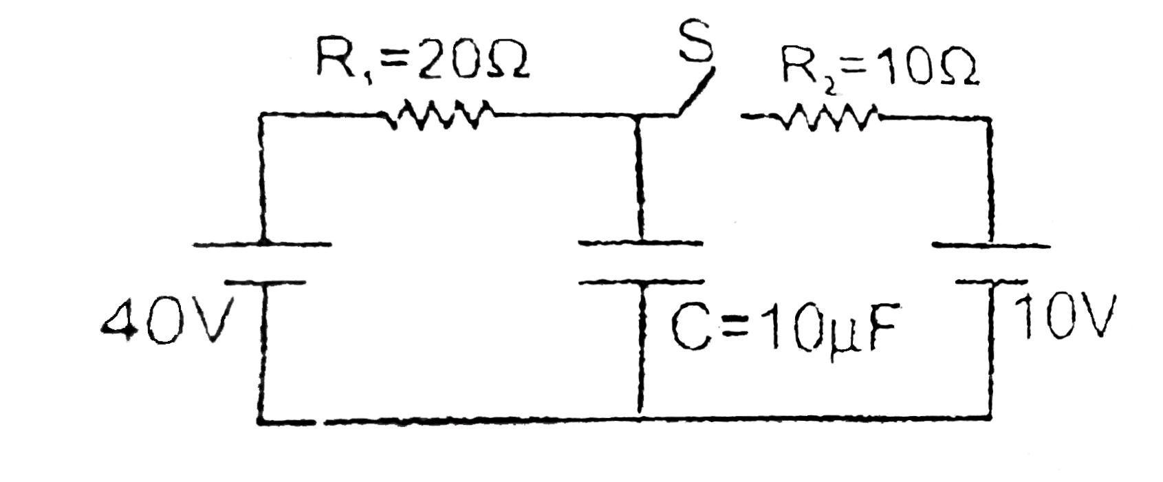
The charge on capacitor in steady state with switch S closed.View SolutionThe circuit consists of two resistors (of resistance R1=20Ω and R2=10Ω), a capacitor (of capacitance C=10μF) and two ideal cells. In the circuit shown the capacitor is in steady state and the switch S is open
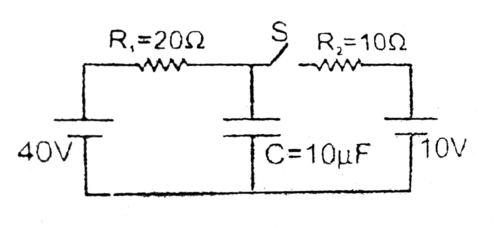
The current through the resistor R2 just after the switch S is closed is :View SolutionA series LCR circuit, has equal resistance capacitive reactance. What is the phase angle between voltage across generator and resistor ?
View SolutionFor the circuit shown in figure, determine the voltage across 4Ω resistors in volt ?
 View Solution
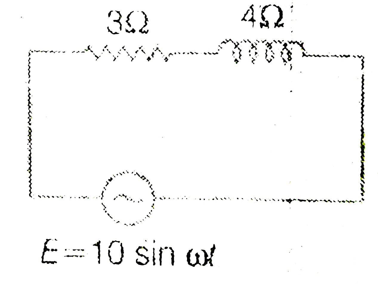
An ac-circuit having supply voltage E consists of a resistor of resistance 3Ω and an inductor of reactance 4Ω as shown in the figure. The voltage across the resistane at t=πω is
 View Solution

