Two resistors of resistances 10Ω and 40Ω are connected with a capacitor of capacitance 0.1μF and ideal battery of emf 10 V. When switch (S) is closed, then initial current and current in steady state through the battery respectively are 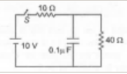
1A, 1A
0.1A, 0.2 A
1 A, 0.2 A
0.2 A, 1A
Step by step video & image solution for Two resistors of resistances 10 Omega and 40 Omega are connected with a capacitor of capacitance 0.1 muF and ideal battery of emf 10 V. When switch (S) is closed, then initial current and current in steady state through the battery respectively are by Physics experts to help you in doubts & scoring excellent marks in Class 12 exams.
Updated on:21/07/2023Topper's Solved these Questions
Similar Questions
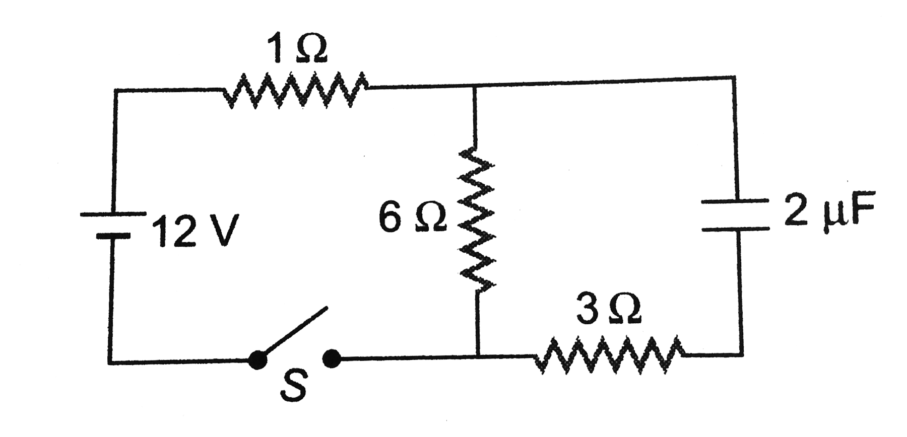
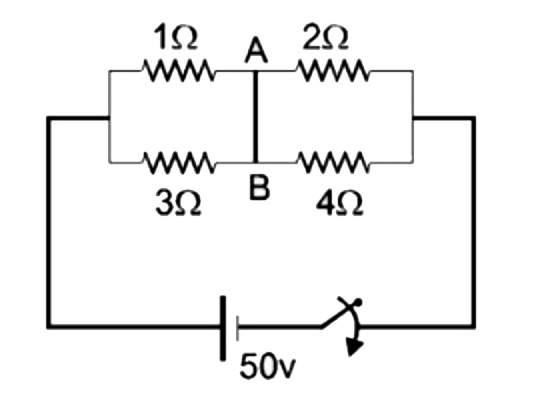
When the switch is closed, the initial current through the 1Ω resistor is
View SolutionThe circuit consists of two resistors (of resistance R1=20Ω and R2=10Ω), a capacitor (of capacitance C=10μF) and two ideal cells. In the circuit shown the capacitor is in steady state and the switch S is open
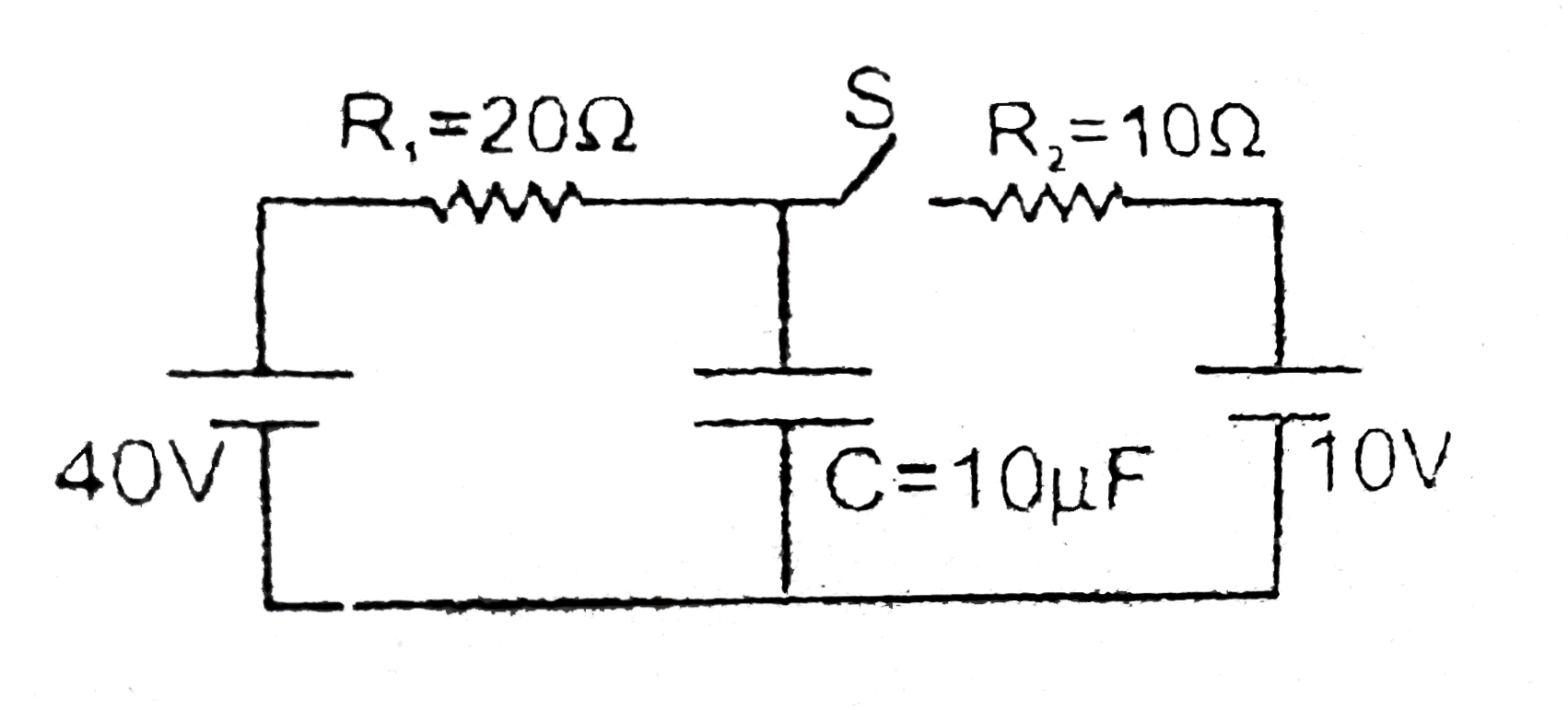
The current through the resistor R2 just after the switch S is closed is :
View Solution
Knowledge Check
Three resistors of resistances 3Ω,4Ωand5Ω are combined in parallel. This combination is connected to a battery of emf 12V and negligible internal resistance, current through each resistor in ampere is
A4,3,2.4B8,7,3,4C2,5,1,8D5,5,8,2
The circuit consists of two resistors (of resistance R1=20Ω and R2=10Ω), a capacitor (of capacitance C=10μF) and two ideal cells. In the circuit shown the capacitor is in steady state and the switch S is open
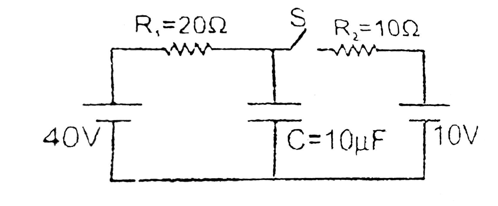
The charge on capacitor in steady state with switch S closed.
View SolutionThe circuit consists of two resistors (of resistance R1=20Ω and R2=10Ω), a capacitor (of capacitance C=10μF) and two ideal cells. In the circuit shown the capacitor is in steady state and the switch S is open
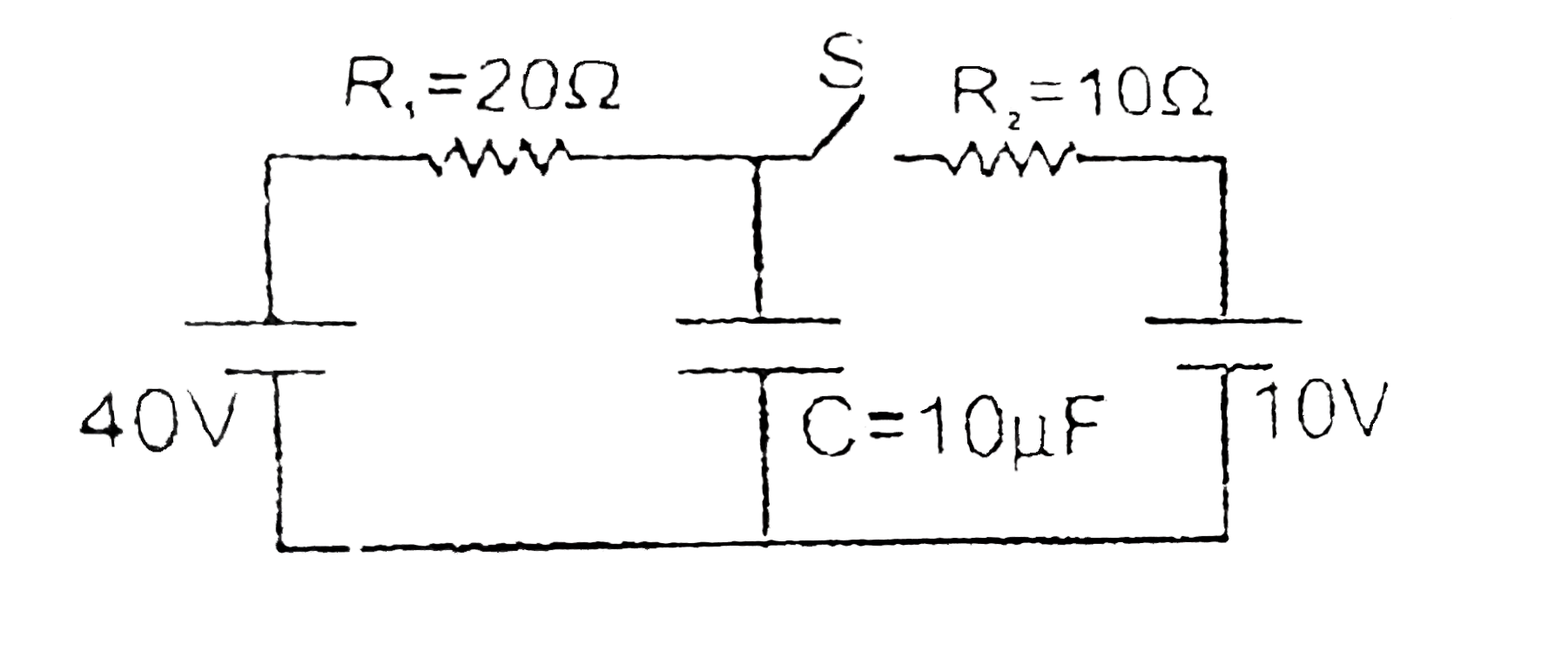
the circuit is in steady state with switch S closed. Now the switch S is opened. Just after the switch S is opened. the current through resistance R1 is
View SolutionTwo resistors of resistances 2Ω and 6Ω are connected in parallel. This combination is then connected to a battery of emf 2 V and internal resistance 0.5Ω. What is the current flowing through the battery ?
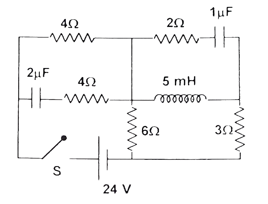
View SolutionIn the circuit shown, the switch 'S' is closed at t=0. Then the current through the battery steady state reached is
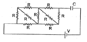
View SolutionIn the circuit shown all the resistors are of same resistance R=11Ω and C=2μF. They are connected through a battery of 10 V. When the cell is switched on, find
(a) maximum current in the circuit, and
(b) energy stored in the capacitor after time t
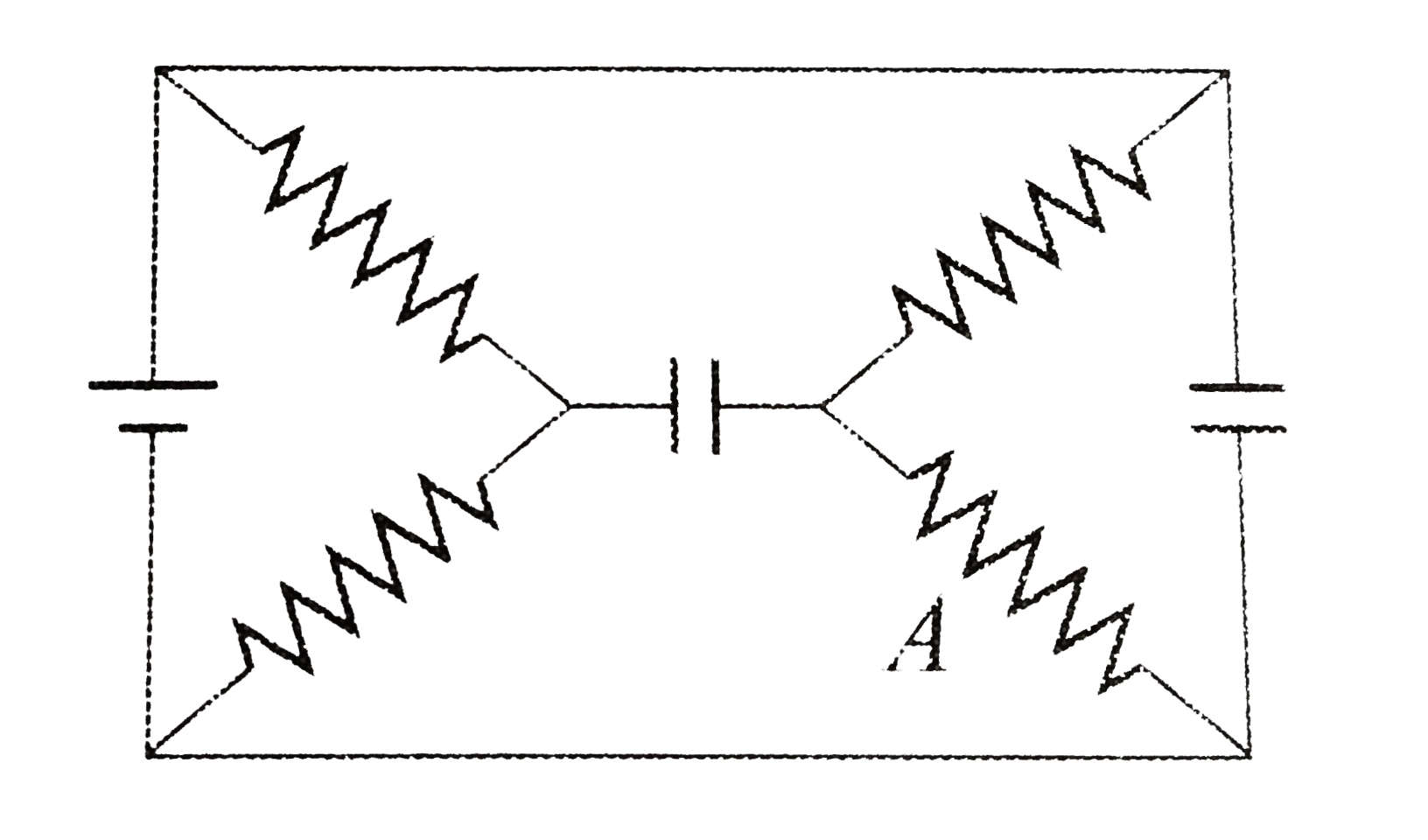
View SolutionEach resistor in the following circuit has a resistance of 2MΩ and the capacitors have capacitances of 1μF. The battery voltage is 3V. The voltage across the resistor A in the following circuit in steady state is
View SolutionFor resistances are connected by an ideal battery of emf 15 V, the circuit is in steady - state then the current (in ampere) in wire AB is :
View Solution
