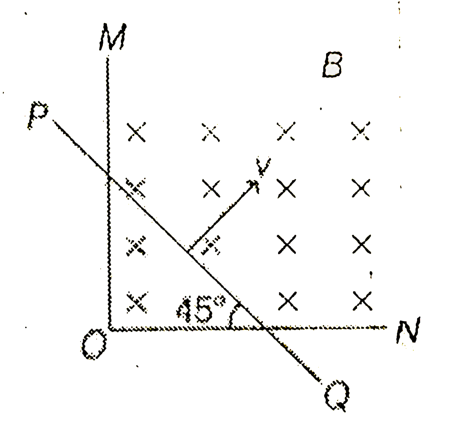
Electric circuit is composed of three conducting rods MO, ON and PQ as shown in the figure. The resistance of the rods per unit length is known to be 1. The rod PQ slides as shown in the figure. At t=0, rod PQ is at O. The whole system is embledded ina uniform magnetic field B, which is directed perpendicularly into page. The induced electric current is:
Proportional to time t
Inversibly proportional to time t
Proportional to square at time t
Independent of time t
The correct Answer is:D
Step by step video, text & image solution for Electric circuit is composed of three conducting rods MO, ON and PQ as shown in the figure. The resistance of the rods per unit length is known to be 1. The rod PQ slides as shown in the figure. At t=0, rod PQ is at O. The whole system is embledded ina uniform magnetic field B, which is directed perpendicularly into page. The induced electric current is: by Physics experts to help you in doubts & scoring excellent marks in Class 12 exams.
Similar Questions
an electric circuit is component of the three conducting rods MO , ON and PQ , as shown in the figure. The resistence of the rods per unit length is λ . The rod PQ slide, as shown in the figure, at a constant velocity v , keeping its tilt angle relative to ON and MO fixed at 45∘ . At each instance the circuit is closed. The whole system is embedded in a uniform magnetic field B , which is directe dperpendicularly into th epage. Compute the time-dependent induced electric current
 View Solution
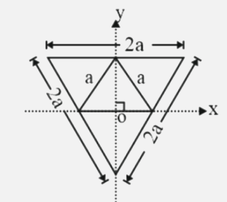
The y co - ordinate of the centre of mass of the system of three rods of length 2a and two rods of length a as shown in the figure is (Assume all rods to be of uniform density)
 View Solution
Knowledge Check
- Question 1 - Select One
A conductor PQ , with PQ=r , moves with a velocity v in a uniform magnetic field of induced B . The emf induced in the rod is
A(→v×→B).→rB→v.(→r×→B)C→B.(→r×→v)D∣∣→r×(→v×→B)∣∣ - Question 2 - Select One
A conducting wheel in which there are four rods of lengthe l as shown in figure is rotating with angular velocity ω in a uniform magnetic field B. The induced potential difference between its centre and rim will be
 A2Bωl2B√Bl2ωCBlω2DBl2ω2
 - Question 3 - Select One
A small conducting rod of length l, moves with a uniform velocity v in a uniform magnetic field B as shown in fig __
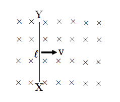 AThen the end X of the rod becomes positively chargedBThe end Y of the rod becomes positively chargedCThe entire rod is unevenly chargedDThe rod becomes hot due to joule heating
A conducting wheel in which there are four rods of length 25 cm as shown in the figure is rotating with constant velocity 20 rad/s in a uniform magnetic field 8 T . The induced potential difference between its centre and rim will be
 View Solution
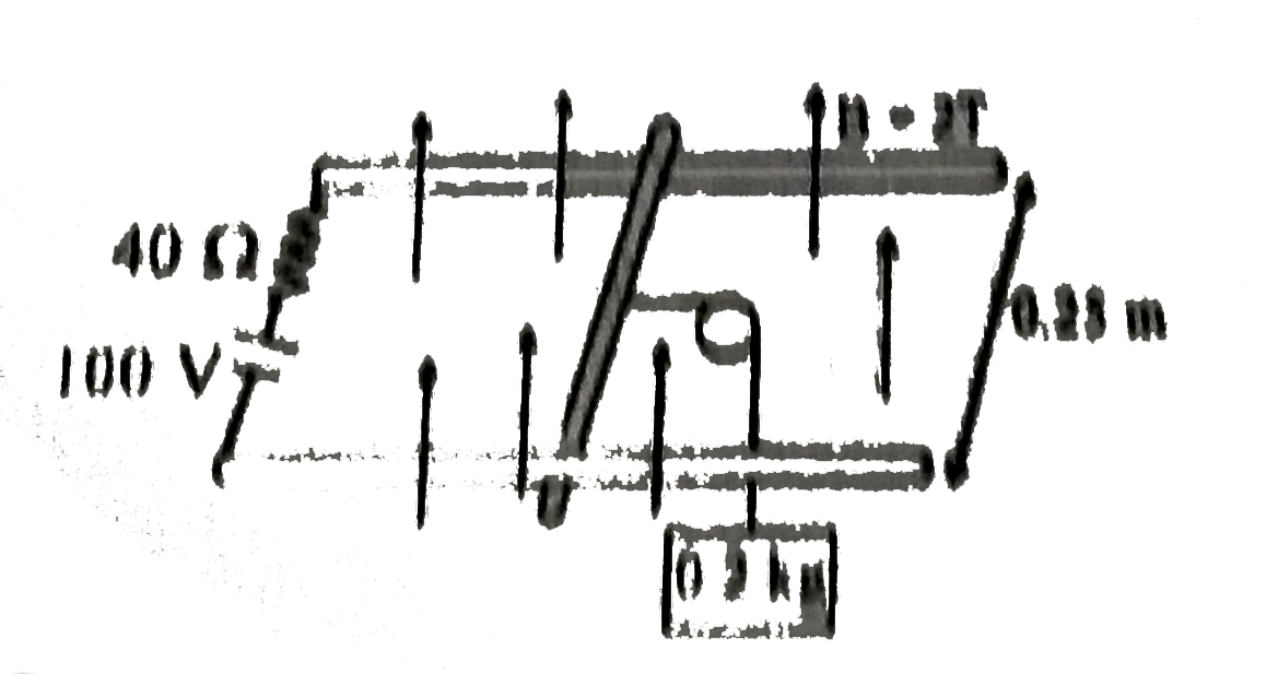
A conducting frame is placed in a horizontal plane as shown in the figure. The two sides are parallel and separated by a distance of 0.25 m. A massless conducting rod can slide without friction on the frame. The total resistance of the circuit is 40 Omega. The rod is connected to a 0.2 kg mass by a massless cord which passes over a massless and frictionless pulley. A uniform magnetic field of 2T points vertically upward. The voltage of the bettery is 100 V. Find the constant velocity in m//s with which the rod and mass eventually move.
 View Solution
A metal rod of length l cuts across a uniform magnetic field B with a velocity v. If the resistance of the circuit of which the rod forms a part is r, then the force required to move the rod is
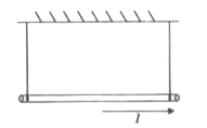
View SolutionAn iron rod of mass 50 g and length 50 cm is suspended by master wires as shown in the figure. Calculate the magnitude and direction of magnetic field to be set in the region such that the tension is the wires is zero. The current in the rod is 4 A.
 View Solution
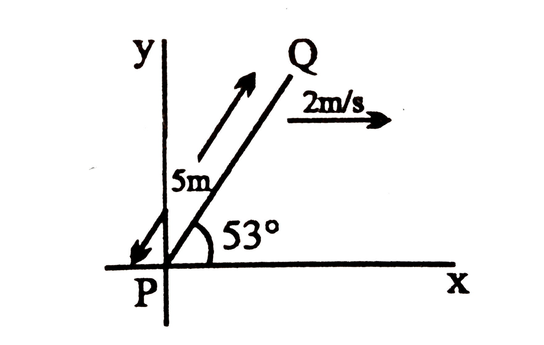
A conducting rod PQ of length 5m oriented as shown in figure is moving with velocity (2m/s)ˆi without any rotation in a uniform magnetic field (3ˆj+4ˆk) Tesla. Emf induced in the rod is
 View Solution

