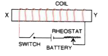
Fig. shows a coil wound around a soft iron bar XY.
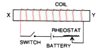
State the polarity at the ends X and Y as the switch is pressed.
X-south pole, Y-north pole.
Topper's Solved these Questions
- MAGNETISM BOOK - ICSECHAPTER - MAGNETISM EXERCISE - EXERCISE-10(B) (Multiple Choice Type)
2 Videos
- MAGNETISM BOOK - ICSECHAPTER - MAGNETISM EXERCISE - EXERCISE-10(A) (Multiple Choice Type)
2 Videos
- LIGHTBOOK - ICSECHAPTER - LIGHTEXERCISE - TOPIC 2 Spherical Mirrors (4 Marks Questions )
9 Videos
- MEASUREMENTS AND EXPERIMENTATION BOOK - ICSECHAPTER - MEASUREMENTS AND EXPERIMENTATION EXERCISE - TOPIC 2 SIMPLE PENDULUM (4 Marks Questions )
1 Videos
Similar Questions
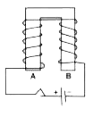
The diagram shows a coil wound around a U shape soft iron bar AB.
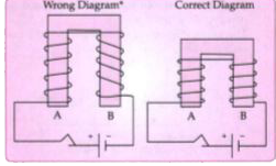
What is the polarity induced at the ends A and B when the switch is pressed ?
View SolutionThe diagram shows a coil wound around a U shape soft iron bar AB.
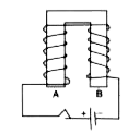
What is the polarity induced at the ends A and B when the switch is pressed ?
View SolutionThe diagram shows a coil wound around a U shape soft iron bar AB.
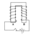
What will be the polarities at A and B if the direction of current is reversed in the circuit ?
View SolutionFig. shows a coil wound around a soft iron bar XY.
Suggest one way of increasing the strength of the electromagnet so formed.
View SolutionThe diagram shows a coil wound around a U shape soft iron bar AB.
Suggest one way to strengthen the magnetic field in the electromagnet.
View SolutionDraw a labelled diagram to make an electro magnet from a soft iron bar AB. Mark the polarity at its ends. What precaution would you observe ?
View SolutionWhen a wire is wound around a soft iron bar, and a current is passed through it, the soft iron bar behaves like a magnet.
View Solution(i) Define a neutral point.
(ii) In the diagram below AB is a magnet and CD is an iron bar.
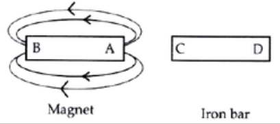
Study the diagram and determine the polarities at the ends A,B and D.
View SolutionA coil of insulated copper wire is wound around a piece of soft iron and current is passed in the coil from a battery. What name is given to the device so obtained ? Give one use of the device mentioned by you.
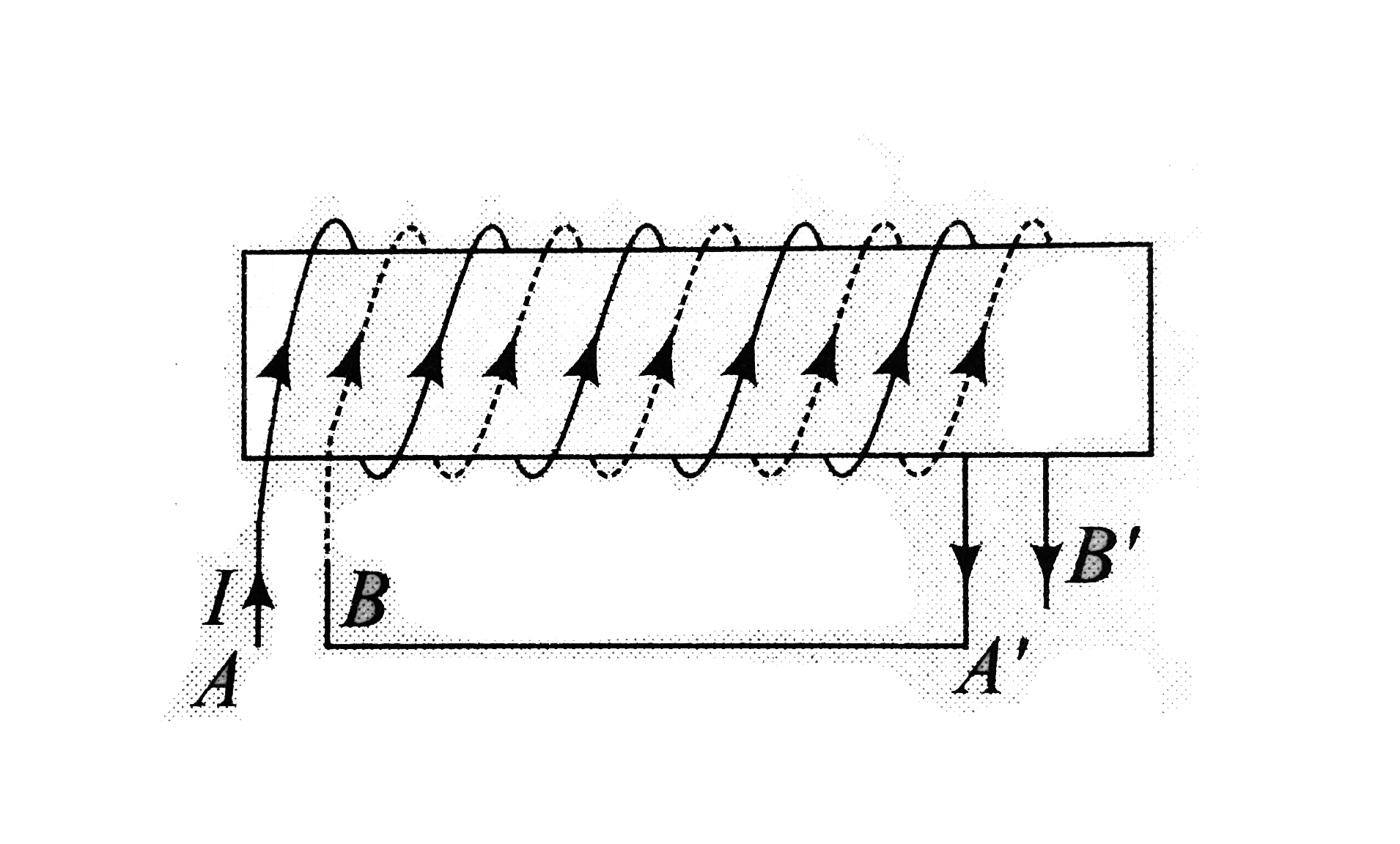
View SolutionIn Fig. coil 1 and coil 2 are wound on a long cylindrical insulator. The ends A' and B are joined together and current I is passed. Self-inductance of the two coils are L1 and L2, and their mutual inductance is M.
a. Show that this combination can be replaced by a single coil of equivalent inductange given by
Leq=L1+L2+2M.
b. How could the coils be reconnected by yieldings an equivalent inductance of Leq=L1+L2−2M.
View Solution
