Figure shows a small magnetised needle P placed at a point O. The arrow shows the direction of its magnetic moment. Te other arrows show different positions (and orientations of the magnetic moment) of another identical magnetised needle Q.
Which configuration corresponds to the lowest potential energy among all the configurations shown ?
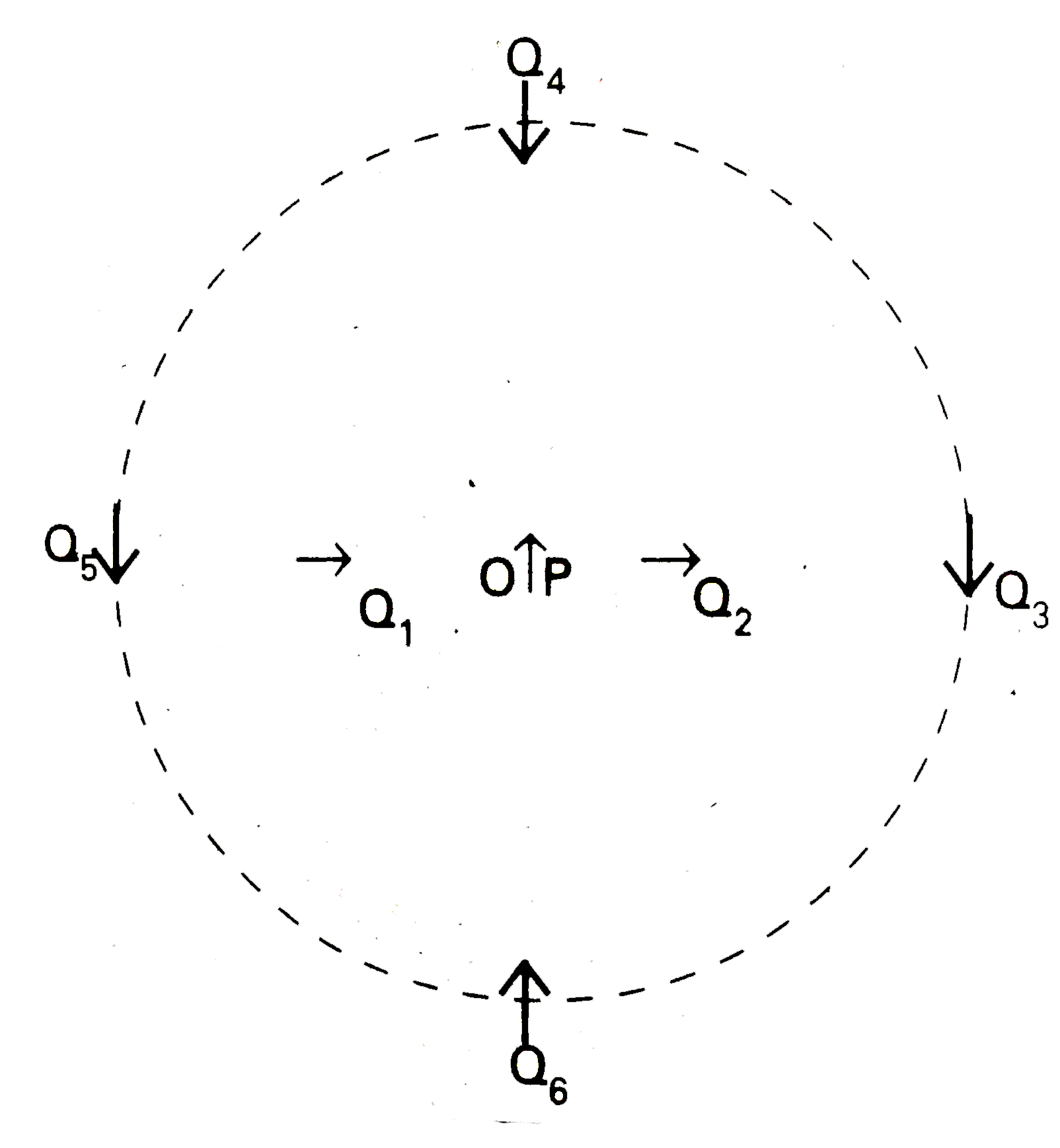
Potential energy of the configuration arises due to the potential energy of one dipole (say, Q) in the magnetic field due to other (P). Use the result that the field due to P is given by the expression.
BP=−μ04πmPr3 (on the normal bisector)
BP=μ024πmPr3 (on the axis)
where mP is the magnetic moment of the dipole P.
Equilibrium is stable whem MQ is parallel to BP, and unstable when it is anti-parallel to BP. For instance for the configuration Q3 for which Q is along the perpendicular bisector of the dipole P, the magnetic moment of Q is parallel to the magnetic field at the position 3. Hence Q3 is stable. Thus,
PQ6.
Topper's Solved these Questions
- BOOK - VIKRAM PUBLICATION ( ANDHRA PUBLICATION)CHAPTER - MAGNETISM AND MATTEREXERCISE - Very Short Answer Questions20videos
MAGNETISM AND MATTER
- BOOK - VIKRAM PUBLICATION ( ANDHRA PUBLICATION)CHAPTER - MAGNETISM AND MATTEREXERCISE - Short Answer Questions10videos
MAGNETISM AND MATTER
- BOOK - VIKRAM PUBLICATION ( ANDHRA PUBLICATION)CHAPTER - MAGNETISM AND MATTEREXERCISE - Additional Exercises19videos
MAGNETISM AND MATTER
- BOOK - VIKRAM PUBLICATION ( ANDHRA PUBLICATION)CHAPTER - ELECTROSTATIC POTENTIAL AND CAPACITANCEEXERCISE - SAQs4videos
ELECTROSTATIC POTENTIAL AND CAPACITANCE
- BOOK - VIKRAM PUBLICATION ( ANDHRA PUBLICATION)CHAPTER - MOVING CHARGES AND MAGNETISHMEXERCISE - ADDITIONAL EXERCISES26videos
MOVING CHARGES AND MAGNETISHM
Similar Questions
Figure shows a small magnetised needle P placed at a point O. The arrow shows the direction of magnetic moment. The other arrows show different positions (and orientations of the magnetic moment) of another identical magnetised needle Q.
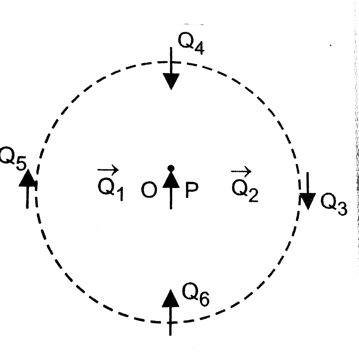
(a) In which configuration is the system not in equilibrium?
(b) In which configuration is the system in (i) stable and (ii) unstable equilibrium?
(c) Which configuration corresponds to the lowest potential energy among all the configurations shown?View SolutionFigure shows a small magnetised needle P placed at a point O. The arrow shows the direction of magnetic moment. The other arrows show different positions (and orientations of the magnetic moment) of another identical magnetised needle Q.

(a) In which configuration is the system not in equilibrium?
(b) In which configuration is the system in (i) stable and (ii) unstable equilibrium?
(c) Which configuration corresponds to the lowest potential energy among all the configurations shown?View Solution
Knowledge Check
- Question 1 - Select One
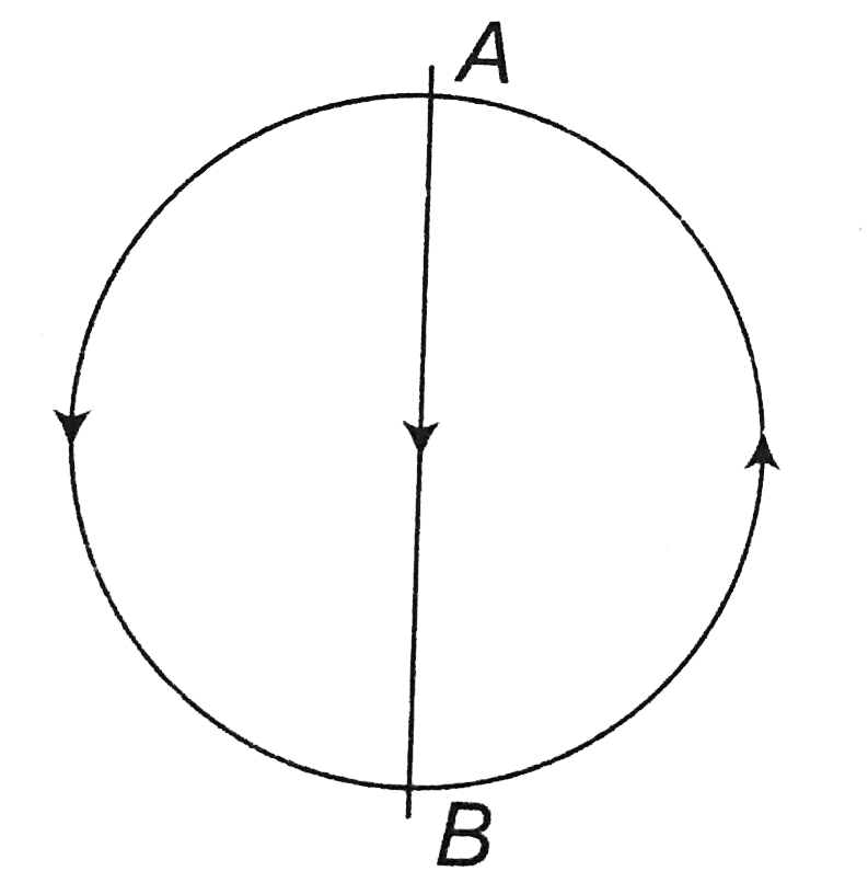
The figure shows a circular coil and a long straight wire AB placed close to each other, the wire being parallel to a diameter of coil. The arrows show directions of currents. The direction of magnetic force acting on AB is
 Aout of the pageBinto the pageCtowards rightDtowards left
 - Question 2 - Select One
Following figures show the arrangement of bar magnets in different configuration . Each magnet has magnetic dipole moment m. Which configuration has highest net magnetic dipole moment ?
A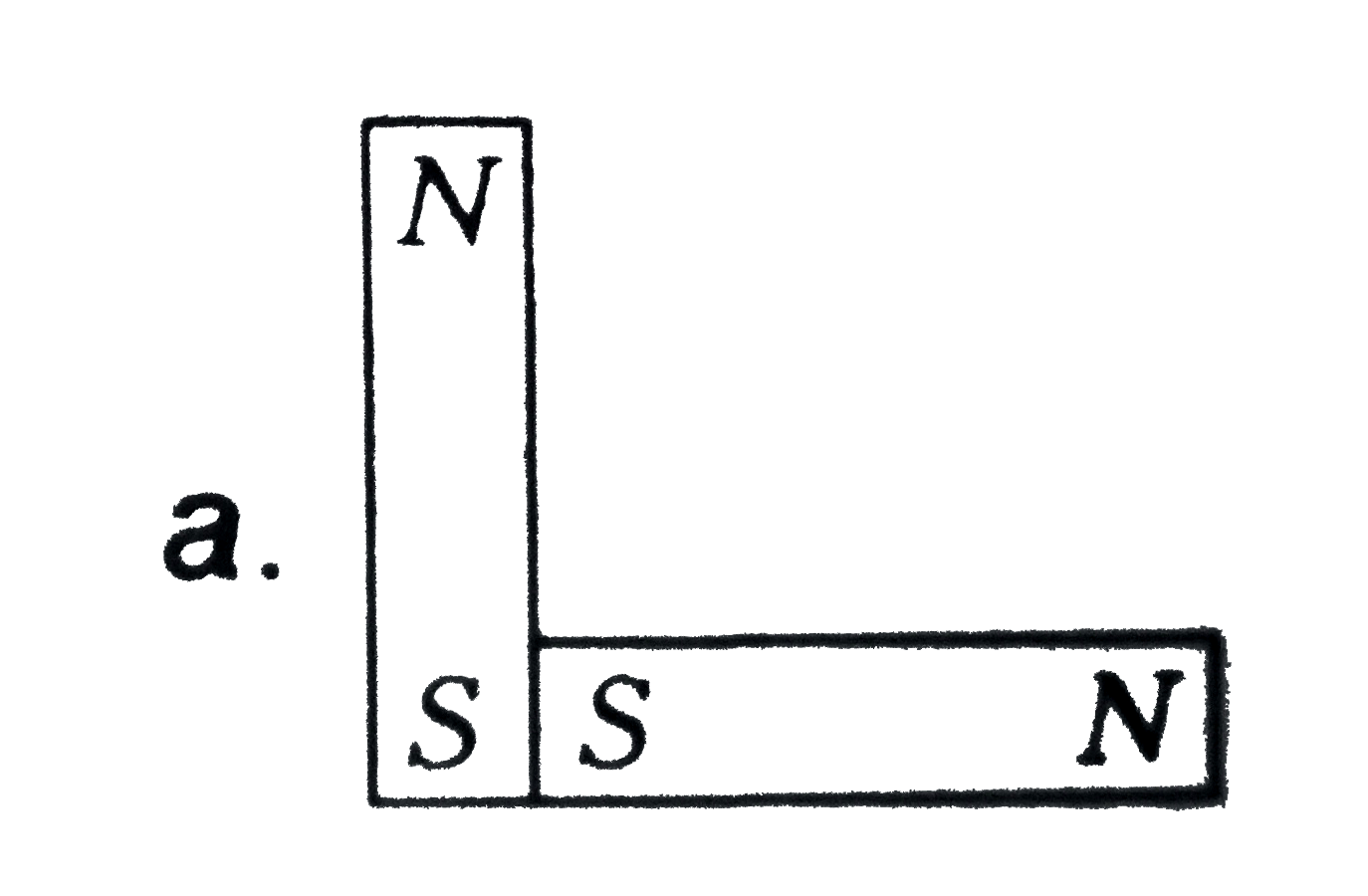 B
B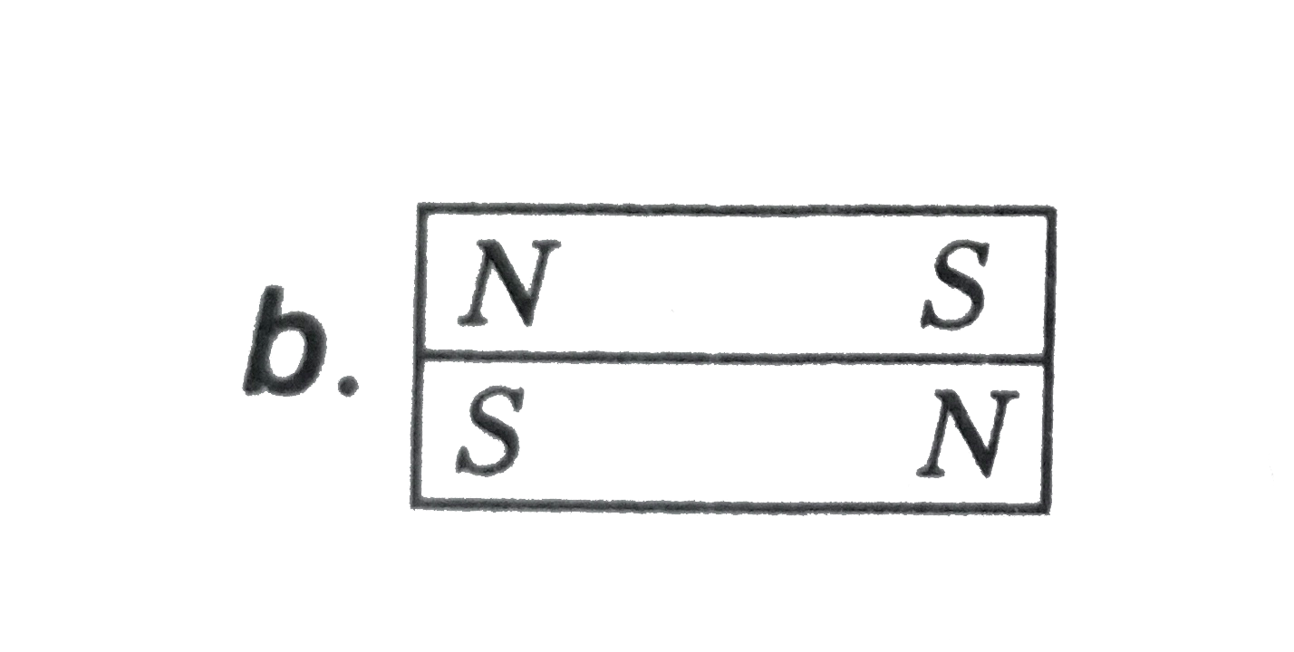 C
C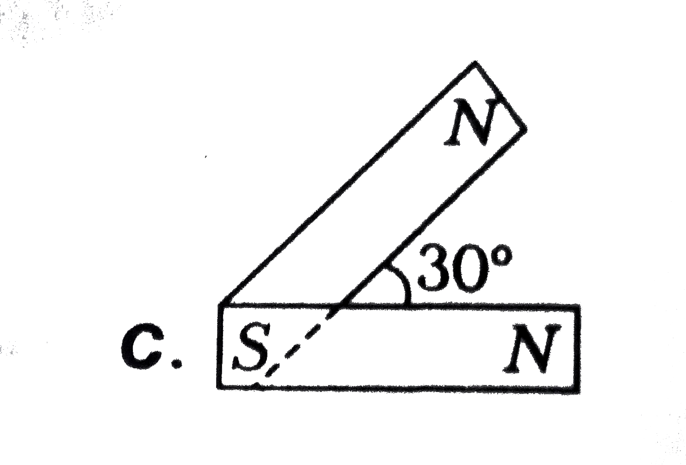 D
D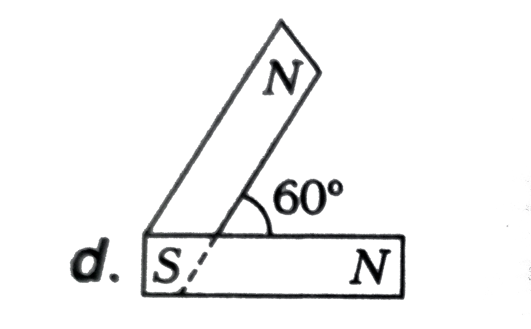
Figure shows a small magnetized needle P placed at a point O. The arrow shows the direction of magnetic moment. The other arrows show different positions (and orientations of the magnetic moment) of another identical magnetized needle Q.

(a) In which configuration is the system not in equilibrium?
(b) In which configuration is the system in (i) stable and (ii) unstable equilibrium?
(c) Which configuration corresponds to the lowest potential energy among all the configurations shown?View SolutionFigure shows a small magnetised needle P placed at a point O. The arrow shows the direction of magnetic moment. The other arrows show different positions (and orientations of the magnetic moment) of another identical magnetised needle Q.

(a) In which configuration is the system not in equilibrium?
(b) In which configuration is the system in (i) stable and (ii) unstable equilibrium?
(c) Which configuration corresponds to the lowest potential energy among all the configurations shown?View SolutionFigure shows a small magnetised needle P placed at a point O. The arrow shows the direction of magnetic moment. The other arrows show different positions (and orientations of the magnetic moment) of another identical magnetised needle Q.

(a) In which configuration is the system not in equilibrium?
(b) In which configuration is the system in (i) stable and (ii) unstable equilibrium?
(c) Which configuration corresponds to the lowest potential energy among all the configurations shown?View SolutionConsider the situation shown in the diagram, where A small magnetised needle A is placed at a centre marked, as O. The direction of its mangetic moment I s indicated by arrow. The other arrow show different position (and orientations of the magnetic moment) of antoher identical magnetised eedle X.
In which configuration the system is not in equlibrium?
(ii) In which configuration is the system in (a) stable and (b) unsable equilibrium
(iii) Which configuration corresponds to the lowest potentials energy among all the configuration shown
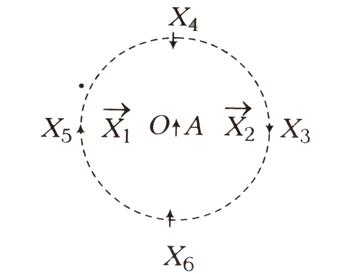 View Solution
Consider the situation shown in the diagram, where A small magnetised needle A is placed at a centre marked, as O. The direction of its mangetic moment I s indicated by arrow. The other arrow show different position (and orientations of the magnetic moment) of antoher identical magnetised eedle X.
In which configuration the system is not in equlibrium?
(ii) In which configuration is the system in (a) stable and (b) unsable equilibrium
(iii) Which configuration corresponds to the lowest potentials energy among all the configuration shown
 View Solution
Fig. shows a bar magnet placed on the table top with its north pole pointing towards south. The arrow shows the north-south direction. There are no other magnets or magnetic material nearby.

Insert two magnetic field lines on either side of the magnet using arrow head to show the direction of each field line.View Solution

