Find power produced in 5Ω resistance in steady state after closing the switch S :

10 W
20 W
30 W
zero
The correct Answer is:D
Step by step video, text & image solution for Find power produced in 5 Omega resistance in steady state after closing the switch S : by Physics experts to help you in doubts & scoring excellent marks in Class 11 exams.
Updated on:21/07/2023Topper's Solved these Questions
- ELECTROSTATICSBOOK - DC PANDEYCHAPTER - ELECTROSTATICSEXERCISE - JEE Advanced
44 Videos
- ELECTROSTATICSBOOK - DC PANDEYCHAPTER - ELECTROSTATICSEXERCISE - Comprehension
36 Videos
- ELASTICITYBOOK - DC PANDEYCHAPTER - ELASTICITYEXERCISE - Medical entrances s gallery
21 Videos
- EXPERIMENTSBOOK - DC PANDEYCHAPTER - EXPERIMENTSEXERCISE - Subjective
15 Videos
Similar Questions
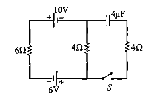
In the circuit shown in figure-3.238, find the current in 6Ω resistance just after closing the switch S.
View SolutionConsider the circuits shown in figure. Find
(a)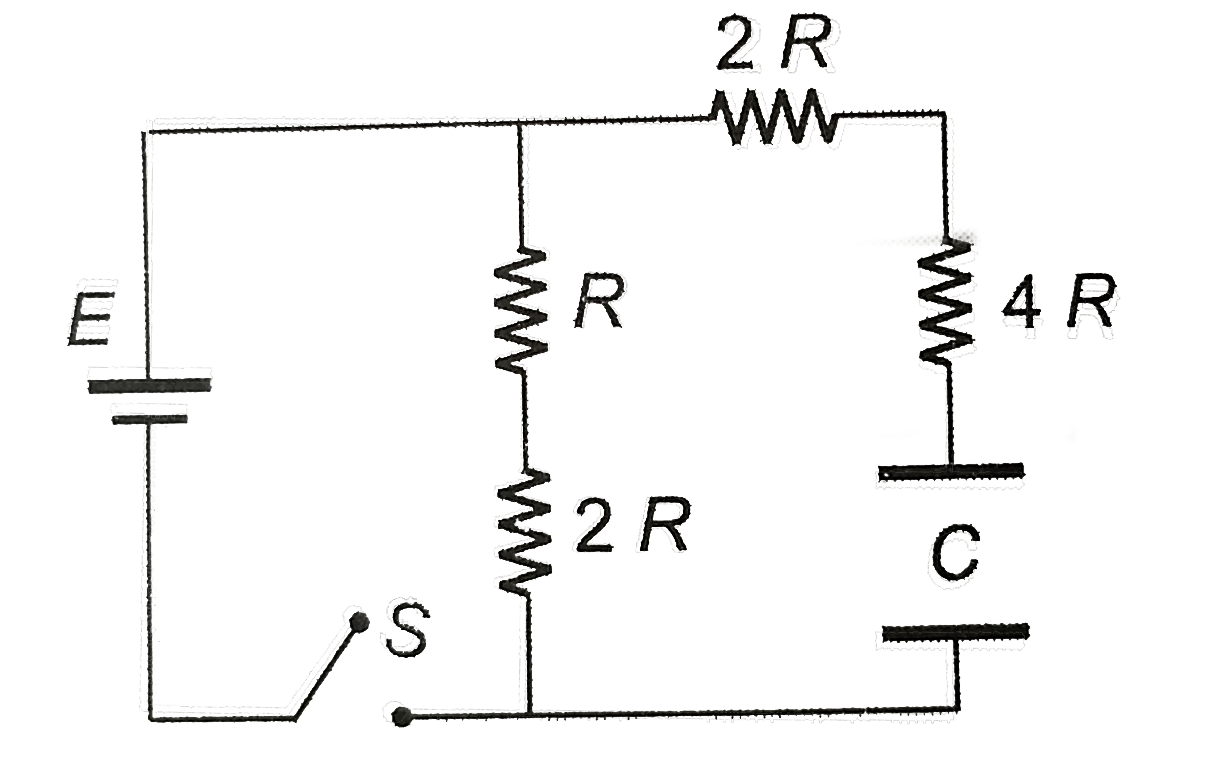
(b)
(c )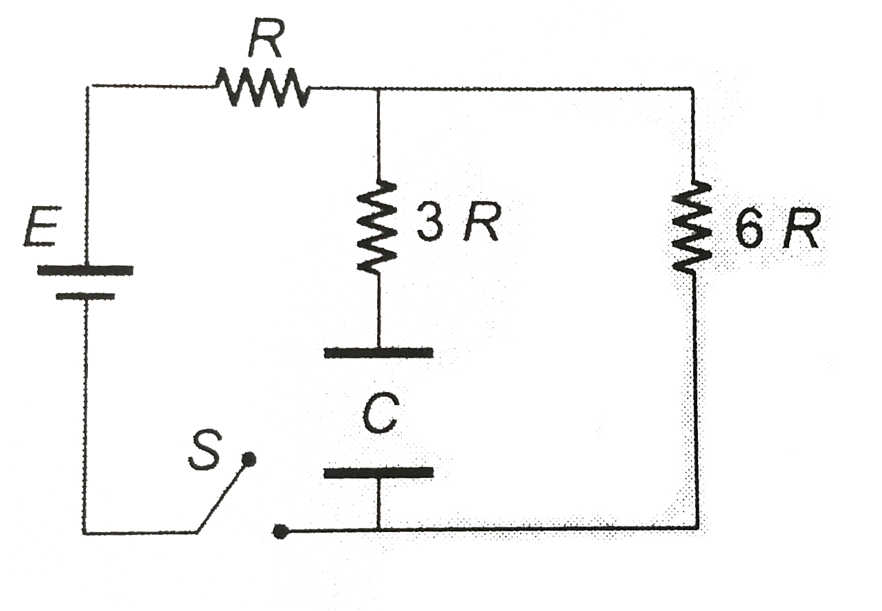
(d)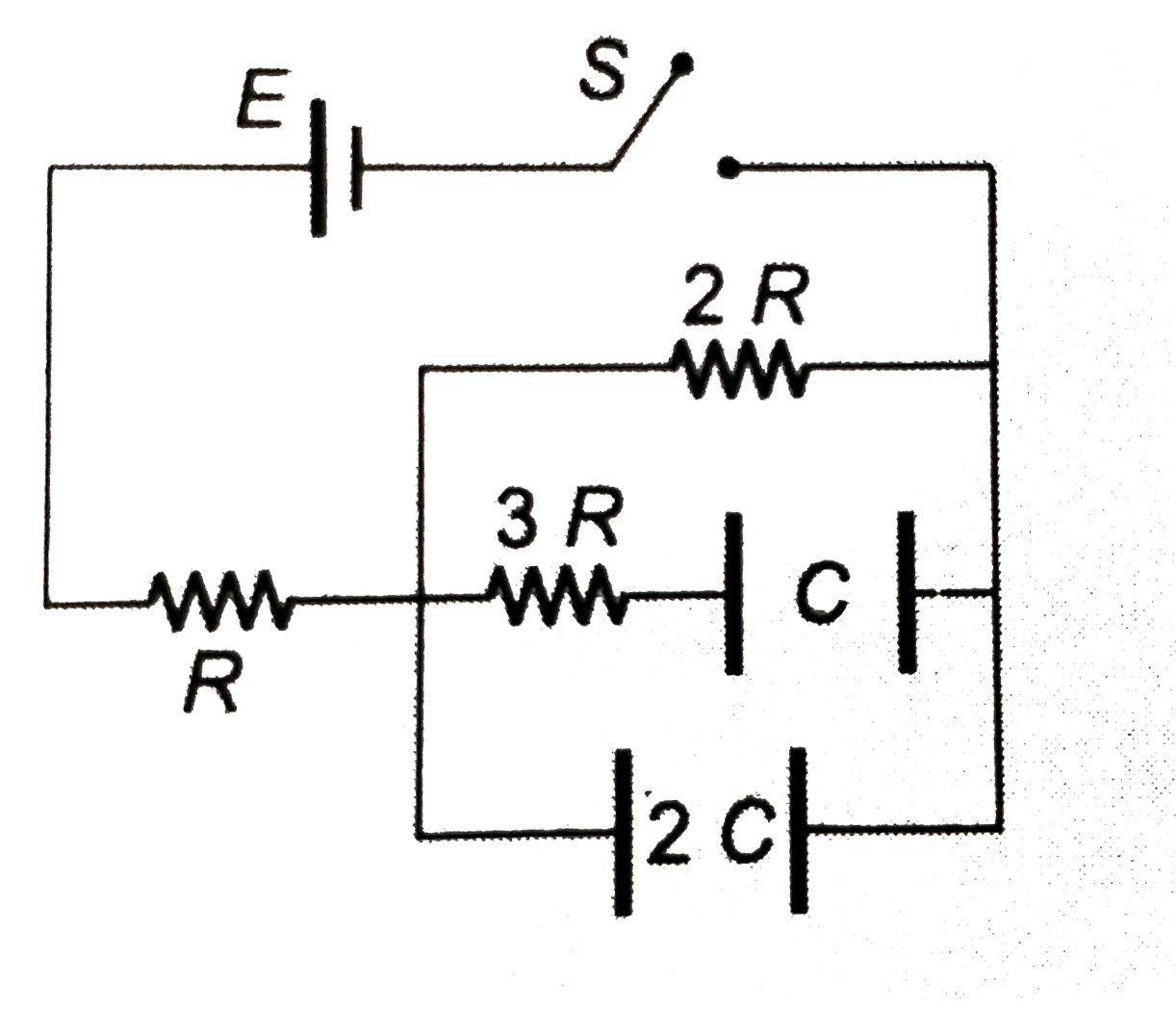
(i) currents through resistances immediately after closing the switch
(ii) Currents through resistaces after a long time ie., steady state.
View Solution
Knowledge Check
Find heaty produced on closing the switch S
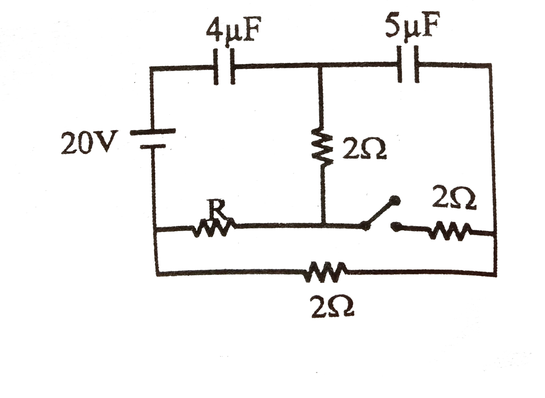 A0.0002JB0.0005JC0.00075Dzero
Find heat produced in the capacitors after long time on closing the switch S
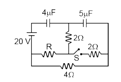 A0.0002JB.0005JC0.00075JDzero
In the circuit shown in figure-3.348 when the switch is closed, the initial current through the 1Ω resistor just after closing the switch is
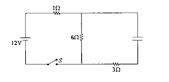 A2AB4AC3AD6A
Find heat produced in the circuit shown in figure on closing the switch S.
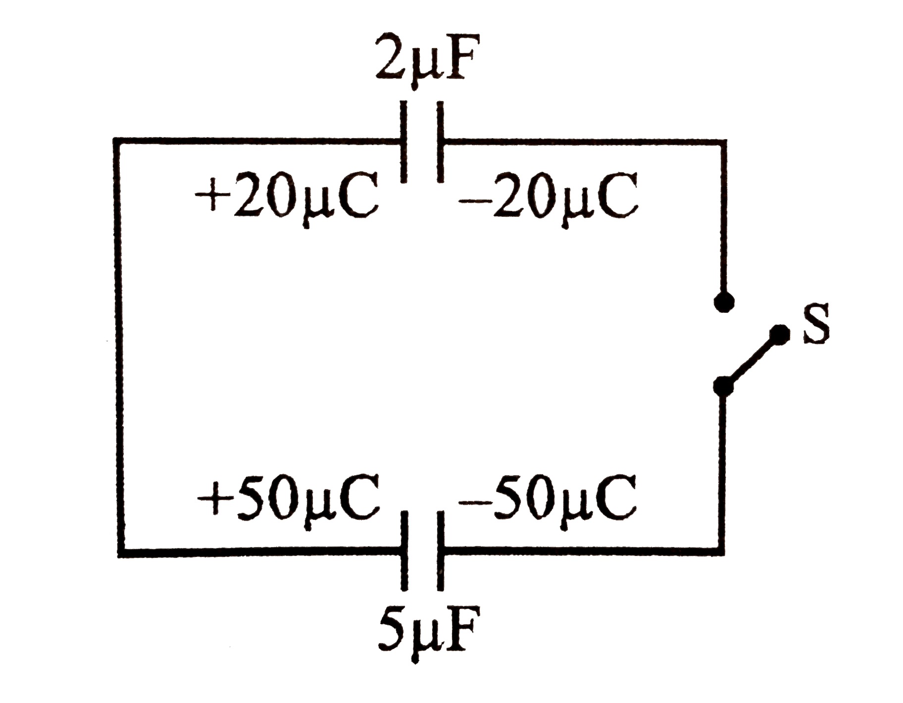
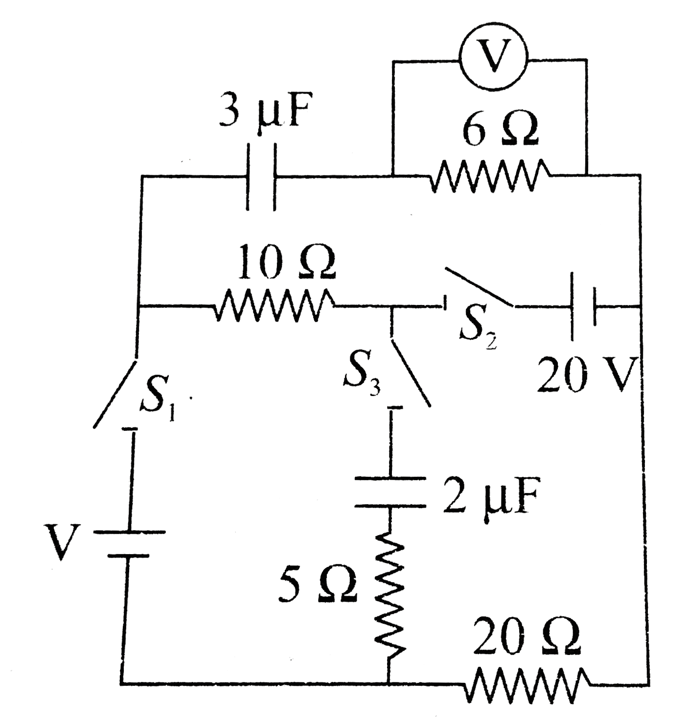
View SolutionOnly switch S1 closed in fig.
a. what is the steady-state reading of the voltmeter?
b. What is the charge on the 3μF capacitor?
c. How much power does the 12V battery supply in the steady state after all the switches are closed?
d. What is the charge on 2μF capacitor?
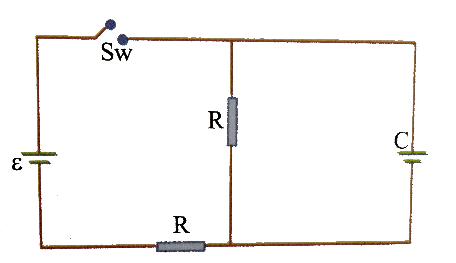
View SolutionFind how the voltage across the capacitor C varies with time t after closing of the switch Sw at the moment t=0.
 .
.
View SolutionThe circuit consists of two resistors (of resistance R1=20Ω and R2=10Ω), a capacitor (of capacitance C=10μF) and two ideal cells. In the circuit shown the capacitor is in steady state and the switch S is open

the circuit is in steady state with switch S closed. Now the switch S is opened. Just after the switch S is opened. the current through resistance R1 is
View SolutionThe circuit consists of two resistors (of resistance R1=20Ω and R2=10Ω), a capacitor (of capacitance C=10μF) and two ideal cells. In the circuit shown the capacitor is in steady state and the switch S is open
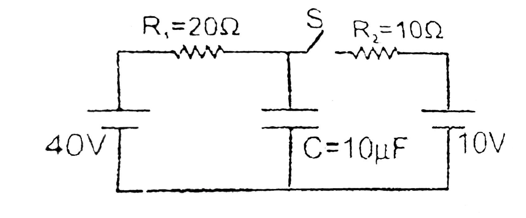
The charge on capacitor in steady state with switch S closed.
View Solution
