For a circuit arrangement shown in figure, energy stored will be 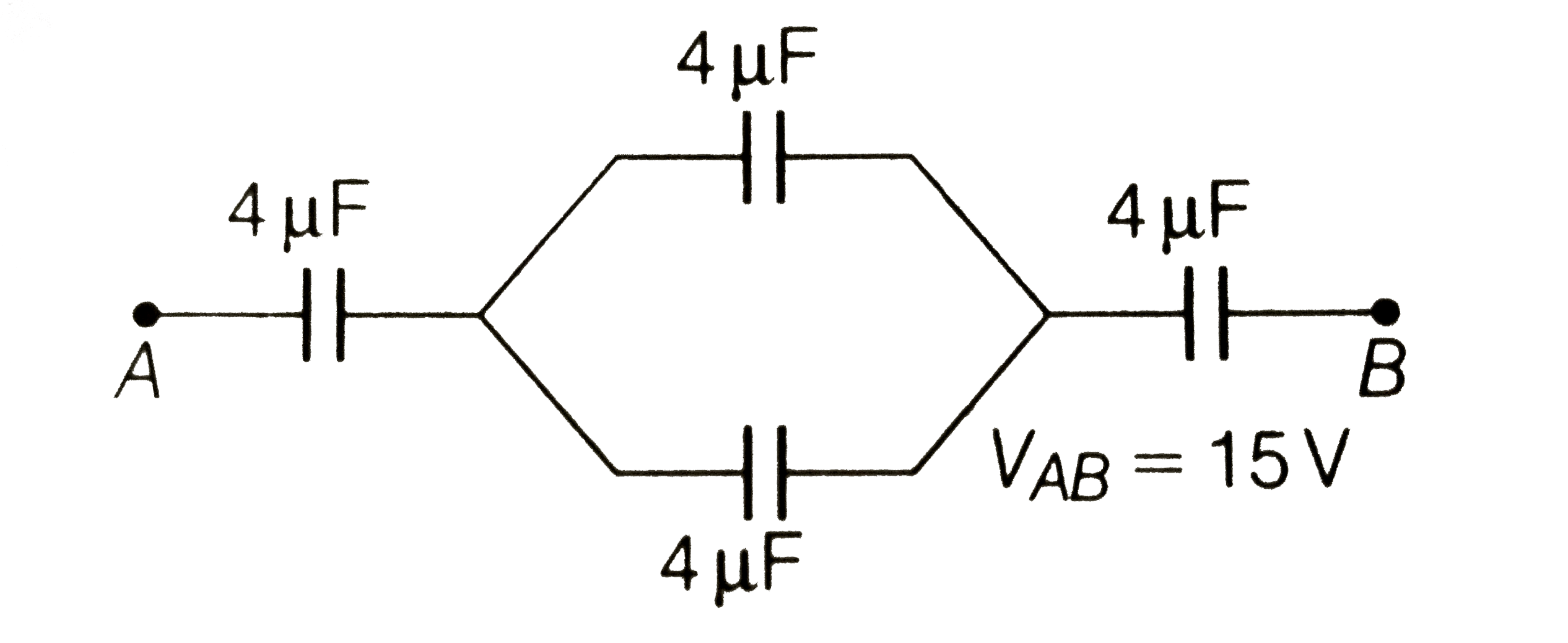
A
0.54 J
B
0.36 J
C
0.24 J
D
0.18 J
Video Solution
Text Solution
The correct Answer is:D
Effective capacitance
1C=14+14+18⇒C=85mF
Energy stored=12CV2
=12×85×10−3×15×15=1.85J
|
Topper's Solved these Questions
Similar Questions
Knowledge Check
For the circuit arrangement shown in figure, in the steady state condition charge on the capacitor is
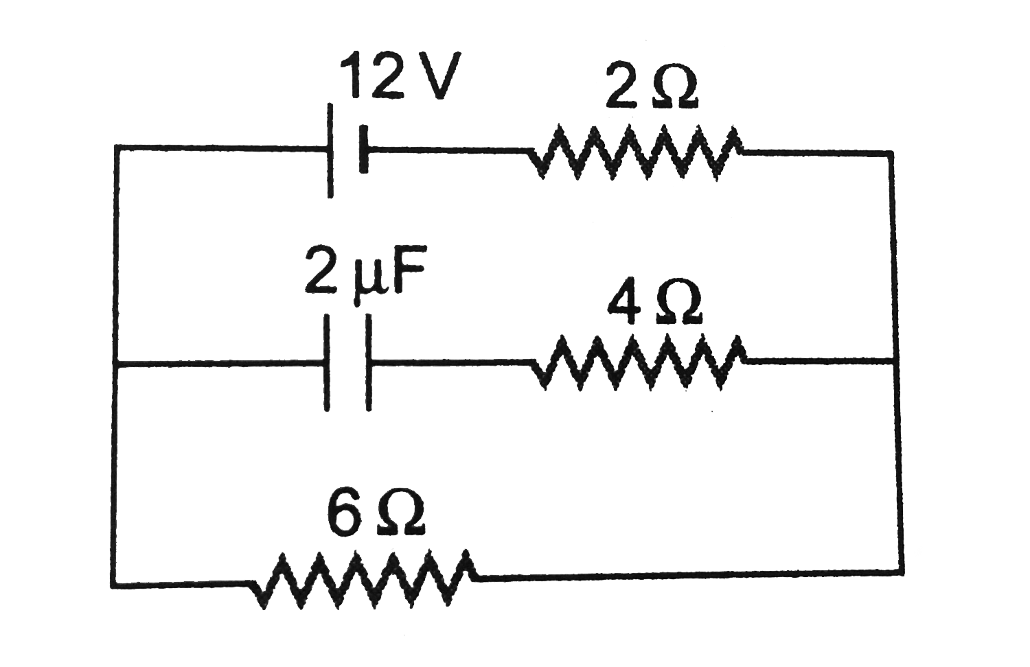 A12μCB14μCC2μCD18μC
The arrangement as shown in figure is called as
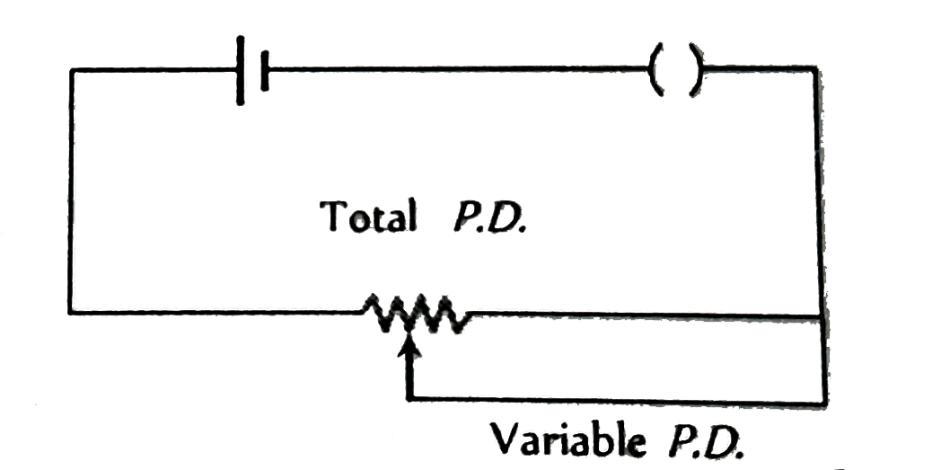 APotential dividerBPotential adderCPotential substracterDPotential multiplier
In LCR circuit as shown in figure
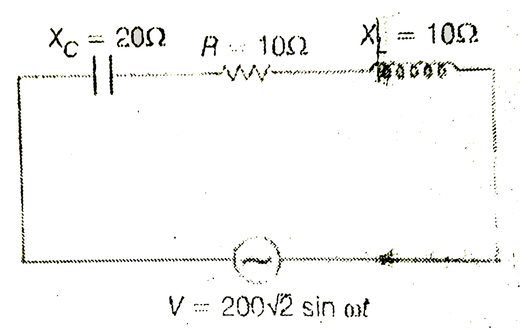 Acurrent will lead the voltageBrms value of current is 20ACpower factor of circuit is 1√2Dvoltage drop across resistance is 100V

