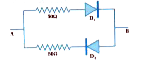
For the circuit shown in the figure, calculate the equivalent resistance for the two cases given as : (1) VA>VBand(2)VB>VA. Here consider D1andD2 to be ideal diodes.
 Solution in Gujrati
50,∞
25, 25
∞,25
25,∞
The correct Answer is:D
25,∞
(i) When VA>VB, then D1andD2 will be formed biased and hence their resistance will be zero and the circuit will be as following.

∴ Equivalent resistance =50×5050+50=25Ω
(ii) When VB>VA, then D1andD2 will be reverse biased and hence their resistance will be ∞ and the circuit will be as following.

∴ Equivalent resistance will be (∞).
Topper's Solved these Questions
- SEMICONDUCTOR ELECTRONICS : MATERIALS, DEVICES AND SIMPLE CIRCUITS BOOK - KUMAR PRAKASHANCHAPTER - SEMICONDUCTOR ELECTRONICS : MATERIALS, DEVICES AND SIMPLE CIRCUITS EXERCISE - Section-D : Multiple Choice Questions (MCQs) (MCQs From .DARPAN. Based On Textbook)
116 Videos
- SAMPLE QUESTION PAPER BOOK - KUMAR PRAKASHANCHAPTER - SAMPLE QUESTION PAPER EXERCISE - PART-B SECTION-C
5 Videos
- WAVE OPTICSBOOK - KUMAR PRAKASHANCHAPTER - WAVE OPTICSEXERCISE - SECTION-D (MULTIPLCE CHOICE QUESTIONS (MCQS)) (MCQS FROM DARPAN BASED ON TEXTBOOK)
239 Videos
Similar Questions
Which of the following is not a conductor of electricity?
View SolutionTwo charges –q and +q are located at points (0, 0, –a) and (0, 0, a), respectively.
(a) What is the electrostatic potential at the points (0, 0, z) and (x, y, 0) ?
(b) Obtain the dependence of potential on the distance r of a point from the origin when r/a>>1 .
(c) How much work is done in moving a small test charge from the point (5,0,0) to (–7,0,0) along the x-axis? Does the answer change if the path of the test charge between the same points is not along the x-axis?
View SolutionAccording to particle theory of light what is the velocity of light in a dense medium, compared to that in rare medium ?
View SolutionIn the following diagram if V_(2) gt V_(1) then
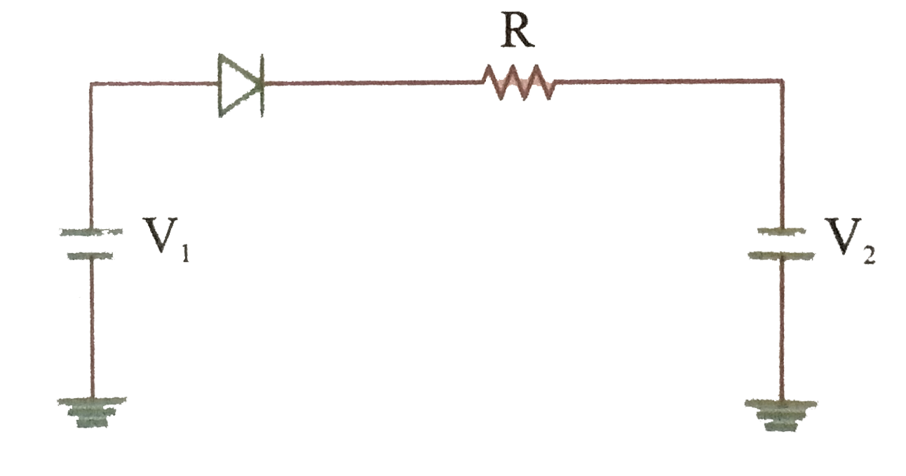
View SolutionIf V1>V2,r is resistance offered by diode in forward bias then current through the diode is.
 .
.
View SolutionIn the circuit shown in figure (1), the V0,I1,ID1, and ID3 are respectively.
(A)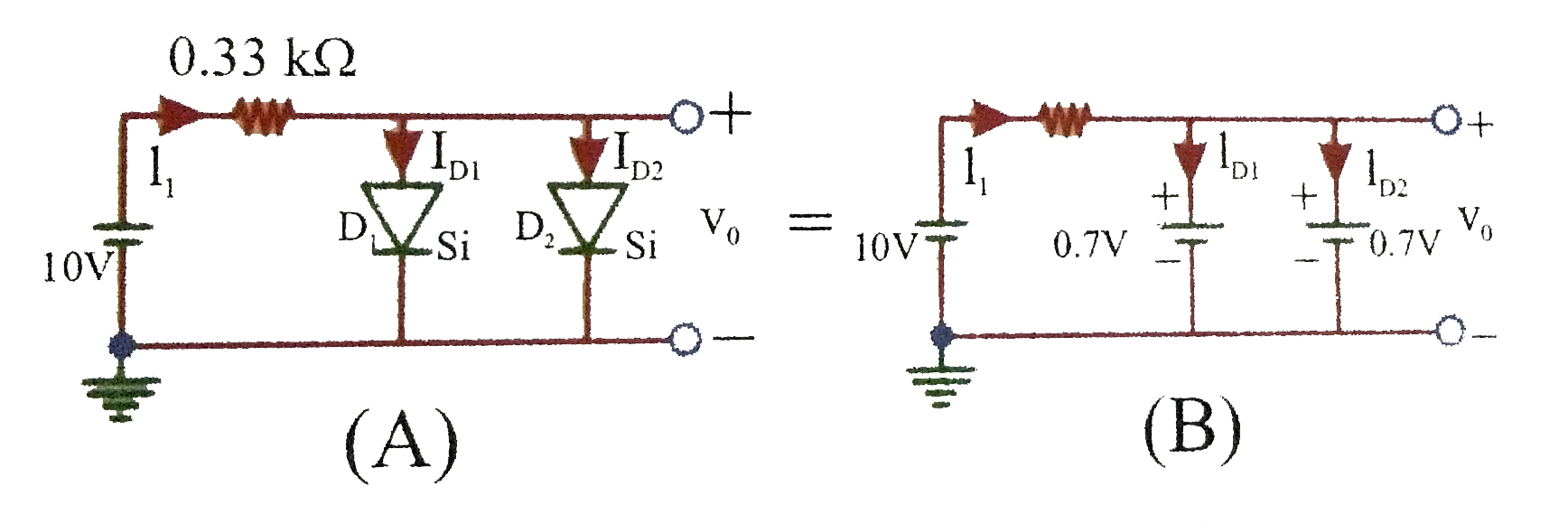
View SolutionV_(A) and V_(B) denote potential of A and B , then the equivalent resistance between A and B in the adjoining circuit is (ideal diode). .
View SolutionTwo capacitors C_(1) and C_(2) in a circuite are joined as shown. If V_(A)=V_(1),V_(B)=V_(2) , the potemntial of point P is
View SolutionA resistance & ideal inductor is connected in the A.C circuit. Here V1,V2&V3 are the reading of three hotwire ideal voltmeter
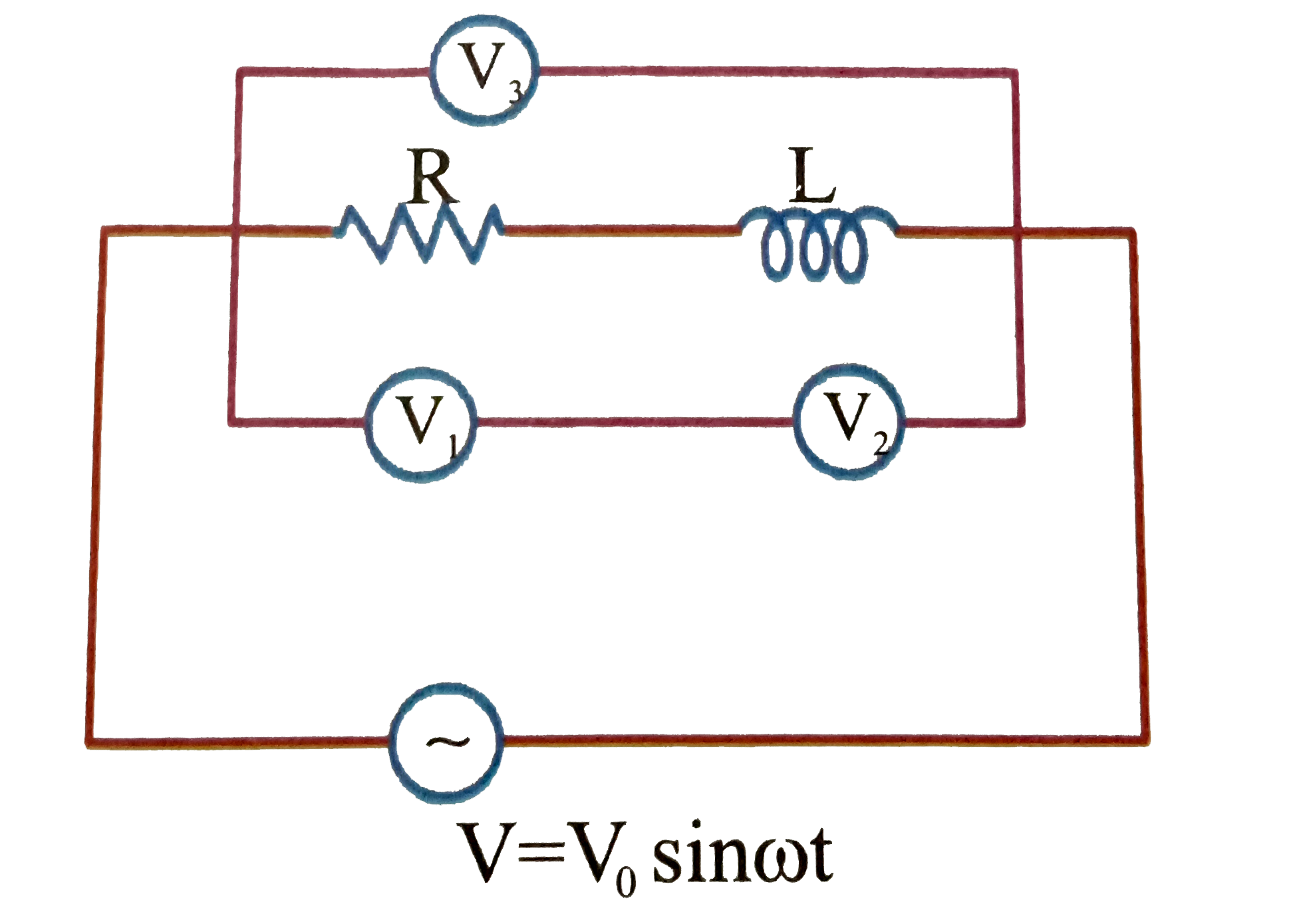
View SolutionConsider the circuit shown in the figure, the cell is ideal. The readings of the ideal voltmeters V_(1) and V_(2) in volts are respectively.
View SolutionThe circuit consists of resistors and ideal cells. I1 and I2 are current through branches indicated in the figure, VA and VB is the potential at points A and B on the circuit
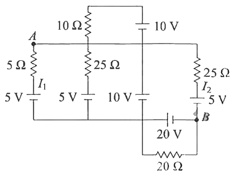
The value of VA−VB in volts is:
View SolutionTwo capacitors C_(1) and C_(2) are connected in a circuit as shown in figure. The potential difference (V_(A) - V_(B)) is
View SolutionFind the equivalent resistance of the network shown in the figure between the points A and B if
(i) VA>VB (ii) VA<VB
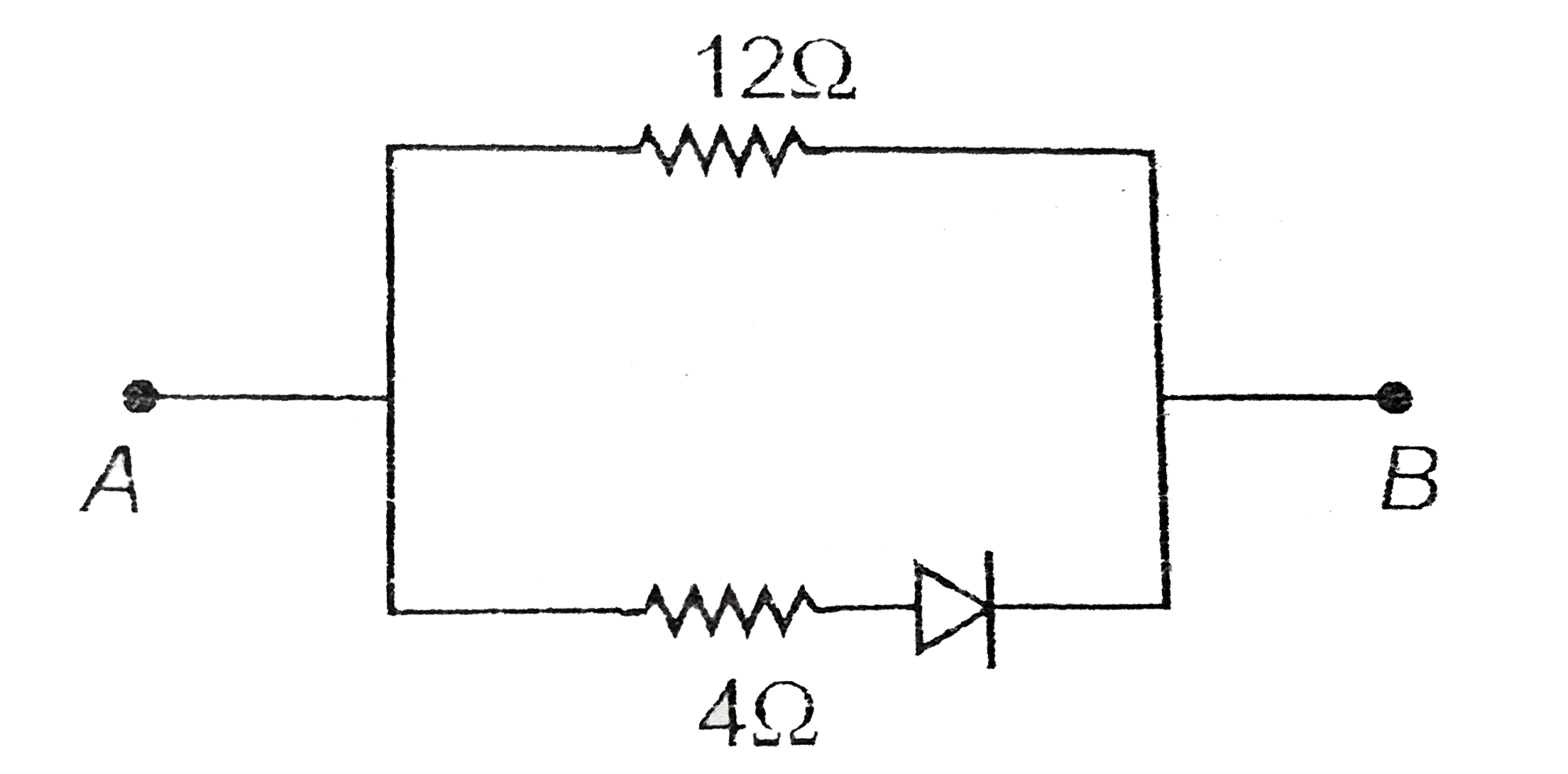
View SolutionV_(A) and V_(B) denot potentils of A and B then the equivalent resistance of A and B, then the equivalent resistance between A and B in the adjoining circuit is (ideal diode)
View Solutionप्रश्न संख्या 27 में, यदि VA>VB हो, तो बिन्दुओं A एवं B के बीच समतुल्य प्रतिरोध होगा-
View SolutionFor the circuit shown in the figure, calculate the equivalent resistance for the two cases given as : (1) V_(A) gt V_(B) and (2) V_(B) gt V_(A) . Here consider D_(1) and D_(2) to be ideal diodes.
View Solution
