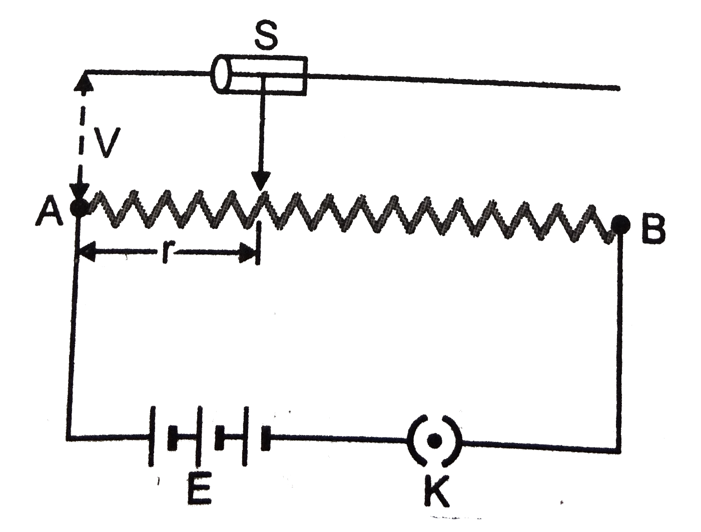
Give the circuit diagram of potential divider.
Video Solution
Text Solution
Rheostat can be used as a potential divider. The circuit diagram for the same in figure. By this arrangement, a desired value of potential difference V can be obtained. The battery of emf, E is connected to the lower terminals A and B of a rheostat through one way key K. The output is taken across A and S, the variable terminal. If R is the resistance of the whole rheostat, between A and B and r is the resistance between A and S, then desired potential difference,
V=ERr.
|
Topper's Solved these Questions
- CURRENT ELECTRICITYBOOK - PRADEEPCHAPTER - CURRENT ELECTRICITYEXERCISE - Conceptual Problems
3 Videos
- CURRENT ELECTRICITYBOOK - PRADEEPCHAPTER - CURRENT ELECTRICITYEXERCISE - Very short Q/A
7 Videos
- COMMUNICATION SYSTEMSBOOK - PRADEEPCHAPTER - COMMUNICATION SYSTEMSEXERCISE - MODEL TEST PAPER-2
9 Videos
- DUAL NATURE OF RADIATION AND MATTERBOOK - PRADEEPCHAPTER - DUAL NATURE OF RADIATION AND MATTEREXERCISE - Exercise
191 Videos
Similar Questions
Knowledge Check
In the circuit diagram shown
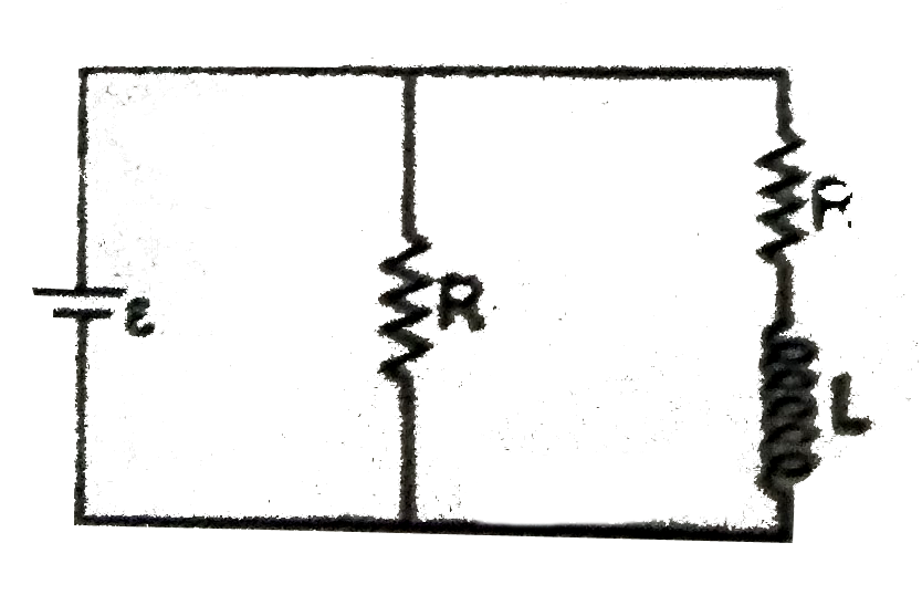 Atime constant is L/RBtime constant is 2L/RCsteady state current in inductor is 2ε/RDsteady state current in inductor is ε/2R
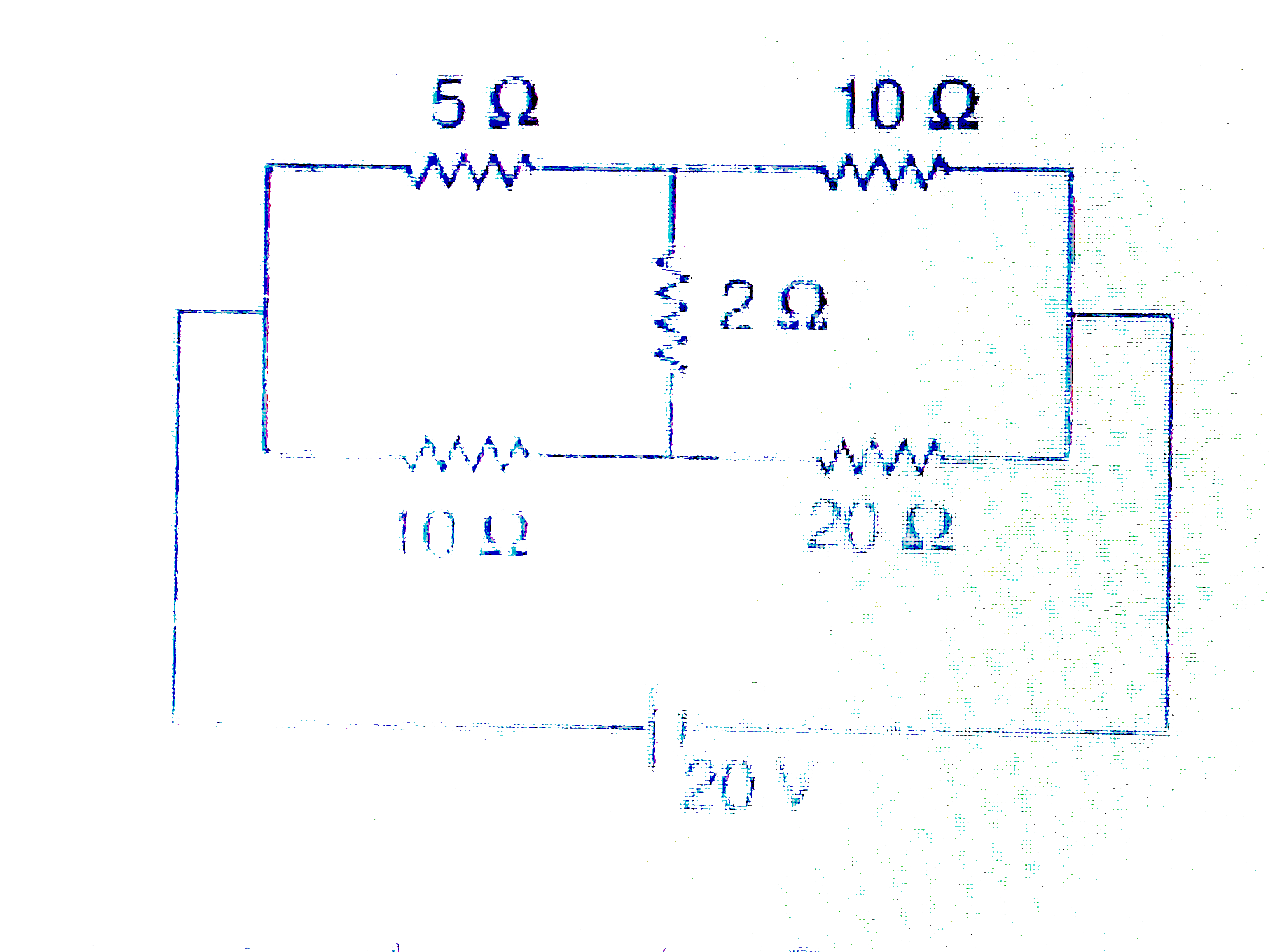
In the given circuit diagram, potential difference across 2Ω resistance is
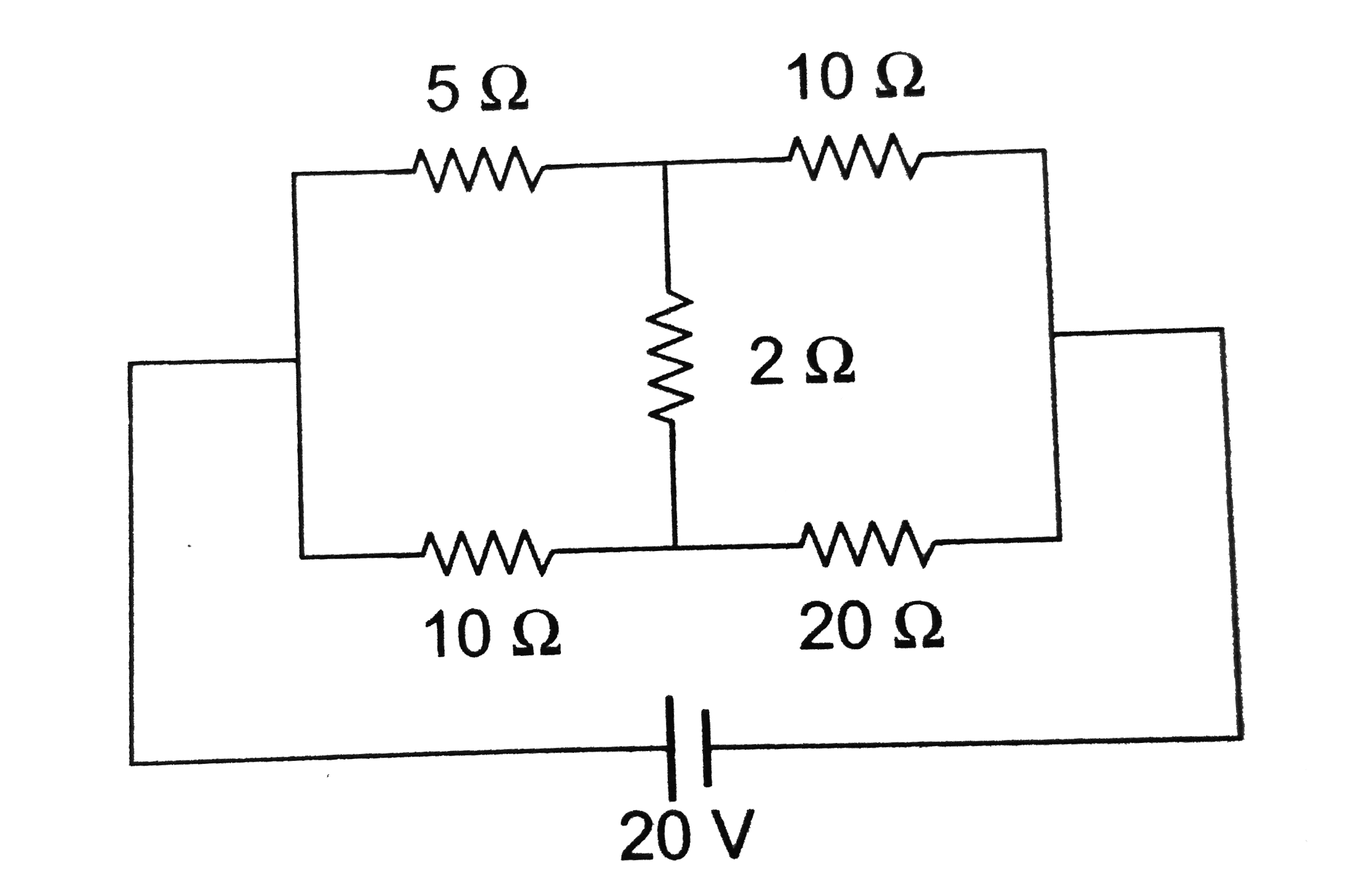 A4VB6VC20VDzero
In the circuit diagram shown in Fi,
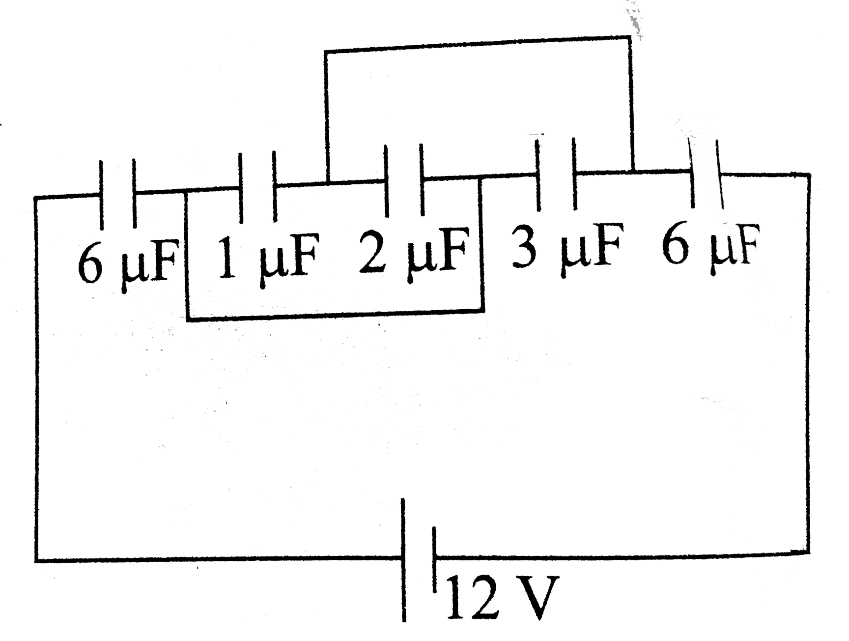 .Athe charge on 2μF capacitor is 8μCBthe charge on each 6μF capacitor is 72μCCthe pottential drop across 1μF capacitor is 4V.Dthe potential drop across 3μF is 4 V
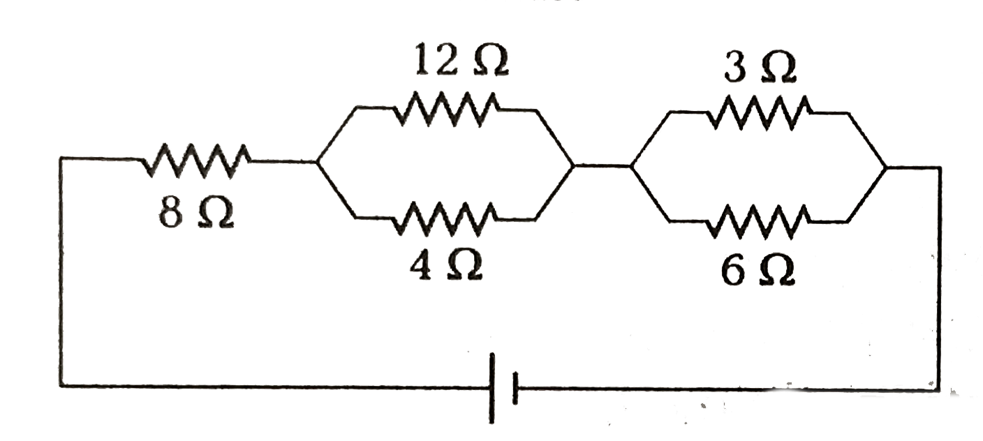
In the circuit diagram shown in figure, potential difference across 3Ω resistance is 20 V. Then, match the following two columns.
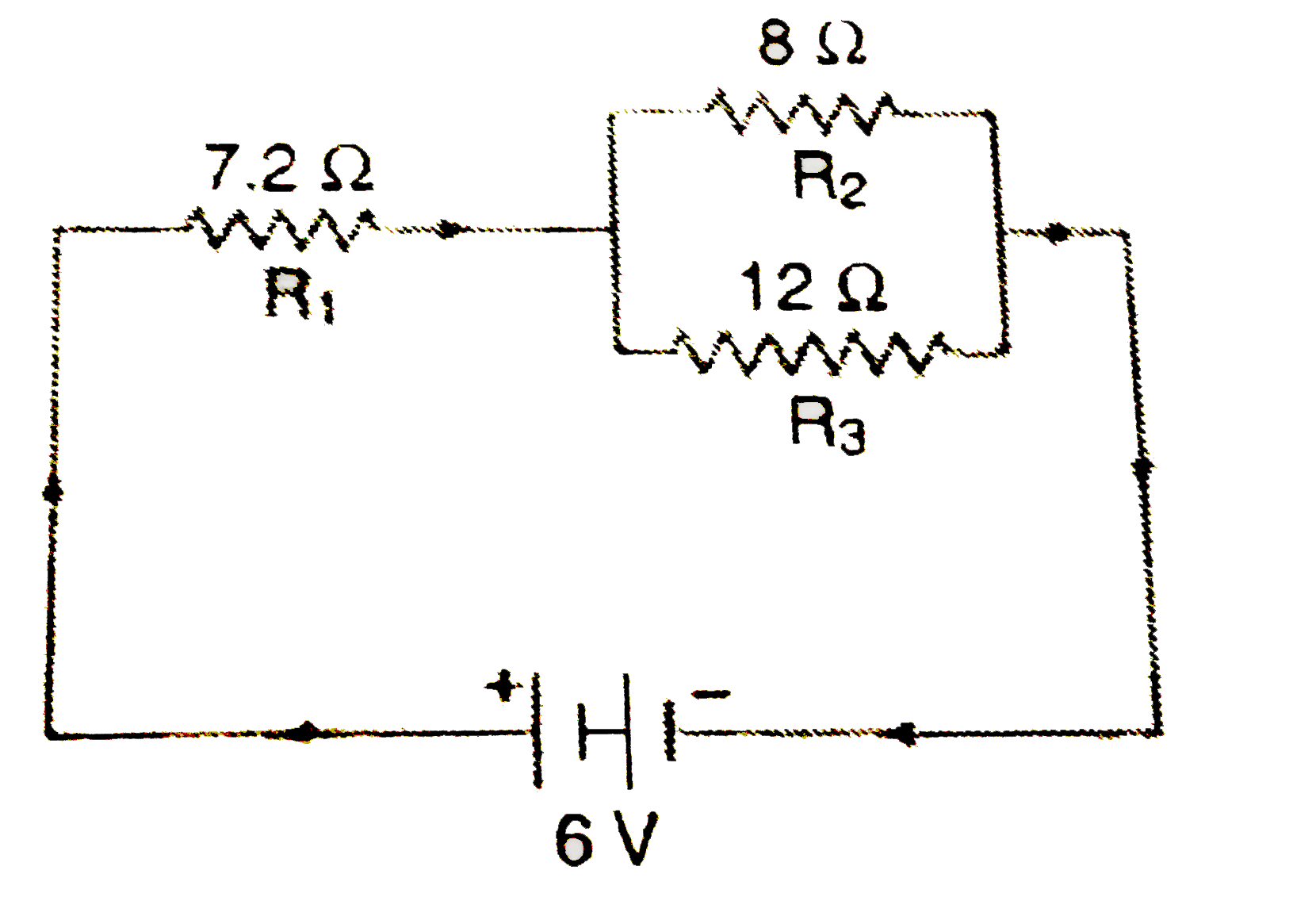
View SolutionIn the circuit diagram given alongside, find:
(i) total resistance of the circuit,
(ii) total current flowing in the circuit, and
(iii) the potential difference across R1
View SolutionDraw the circuit diagram to represent the circuit shown below.
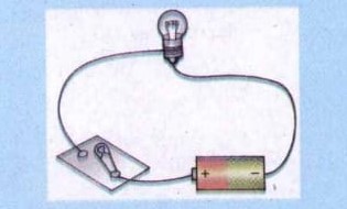
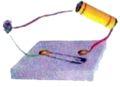
View SolutionDraw the circuit diagram to represent the circuit shown infigure.
View SolutionExplain the formation of depletion layer and potential barrier in p-n junction.
Draw the circuit diagram of a half wave rectifier and explain its working.
View Solution

