Identify the logic gate whose output equals 1 when both of its inputs are 0 each.
To identify the logic gate whose output equals 1 when both of its inputs are 0, we can analyze the behavior of several basic logic gates. Let's denote the inputs as A and B, and the output as Y.
1. Understanding the Inputs:
- We have two inputs, A and B. According to the question, both inputs are 0 (A = 0, B = 0).
2. Analyzing the AND Gate:
- The output of an AND gate is given by the expression Y = A . B (A AND B).
- If A = 0 and B = 0, then Y = 0 . 0 = 0.
- Therefore, the AND gate does not satisfy the condition (output = 1).
3. Analyzing the OR Gate:
- The output of an OR gate is given by the expression Y = A + B (A OR B).
- If A = 0 and B = 0, then Y = 0 + 0 = 0.
- Thus, the OR gate also does not satisfy the condition (output = 1).
4. Analyzing the NAND Gate:
- The output of a NAND gate is given by the expression Y = (A . B)' (NOT of A AND B).
- If A = 0 and B = 0, then Y = (0 . 0)' = 0' = 1.
- Therefore, the NAND gate satisfies the condition (output = 1).
5. Analyzing the NOR Gate:
- The output of a NOR gate is given by the expression Y = (A + B)' (NOT of A OR B).
- If A = 0 and B = 0, then Y = (0 + 0)' = 0' = 1.
- Hence, the NOR gate also satisfies the condition (output = 1).
6. Conclusion:
- Both the NAND gate and the NOR gate output 1 when both inputs are 0.
- Therefore, the answer to the question is that the logic gates whose output equals 1 when both inputs are 0 are the NAND gate and the NOR gate.
- We have two inputs, A and B. According to the question, both inputs are 0 (A = 0, B = 0).
- The output of an AND gate is given by the expression Y = A . B (A AND B).
- If A = 0 and B = 0, then Y = 0 . 0 = 0.
- Therefore, the AND gate does not satisfy the condition (output = 1).
- The output of an OR gate is given by the expression Y = A + B (A OR B).
- If A = 0 and B = 0, then Y = 0 + 0 = 0.
- Thus, the OR gate also does not satisfy the condition (output = 1).
- The output of a NAND gate is given by the expression Y = (A . B)' (NOT of A AND B).
- If A = 0 and B = 0, then Y = (0 . 0)' = 0' = 1.
- Therefore, the NAND gate satisfies the condition (output = 1).
- The output of a NOR gate is given by the expression Y = (A + B)' (NOT of A OR B).
- If A = 0 and B = 0, then Y = (0 + 0)' = 0' = 1.
- Hence, the NOR gate also satisfies the condition (output = 1).
- Both the NAND gate and the NOR gate output 1 when both inputs are 0.
- Therefore, the answer to the question is that the logic gates whose output equals 1 when both inputs are 0 are the NAND gate and the NOR gate.
Topper's Solved these Questions
- XII BOARDSBook:XII BOARD PREVIOUS YEAR PAPER ENGLISHChapter:XII BOARDSExercise:SECTIONS-B
Explore 4 Videos
- XII BOARDSBook:XII BOARD PREVIOUS YEAR PAPER ENGLISHChapter:XII BOARDSExercise:SECTIONS-C
Explore 8 Videos
- XII BOARDSBook:XII BOARD PREVIOUS YEAR PAPER ENGLISHChapter:XII BOARDSExercise:PHYSICS (Theory) DELHI BOARD -2016 [SET -I][COMPTT.]
Explore 11 Videos
- SAMPLE PAPER 2019Book:XII BOARD PREVIOUS YEAR PAPER ENGLISHChapter:SAMPLE PAPER 2019Exercise:SECTION D
Explore 6 Videos
Similar Questions
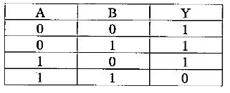
Identify the logic gate whose truth table is given below and draw its symbol :

View SolutionIdentify the pair whose dimensions are equal
View SolutionAn XOR gate produces an output only when its two inputs are :-
View SolutionWhen the inputs of a two input logic gate are 0 and 0, the output is 1. When the inputs are 1 and 0, the output is zero. The type of logic gate is
View SolutionIn the combination of the following gates the output Y can be written in terms of inputs A and B as

View SolutionIt is required to design a (two -input) logic gate, using an appropriate number, of :
(a) NAND gates that gives a 'low' output only when both the inputs are 'low'.
(b) NOR gates that gives a 'high' output only when both the inputs are 'high'.
Draw the logic circuits for these two cases and write the truth table, corresponding to each of the two designs.
View Solution(a) In the figure given below the input waveform is converted into the output waveform by a device 'X'. Name the device and draw its circuit diagram.

(b) Identify the logic gate represented by the circuit as shown and write its truth table.

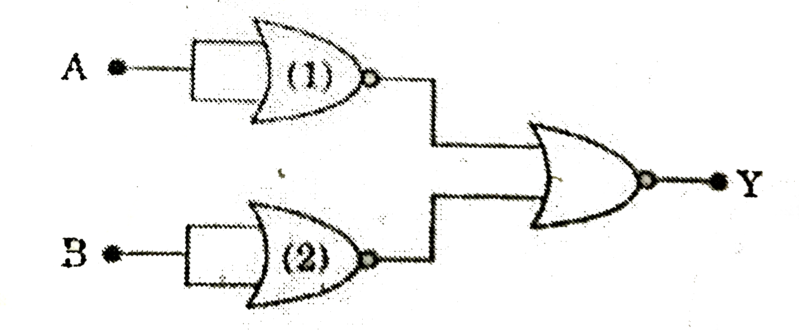
View SolutionThe inputs A and B are inverted by using two NOT gates and their outputs are fed to the NOR gate as shown:
Analyse the action of the gates (1) and (2) and identify the logic gate of the complete circuit so obtained. Give its symbol and the truth table.

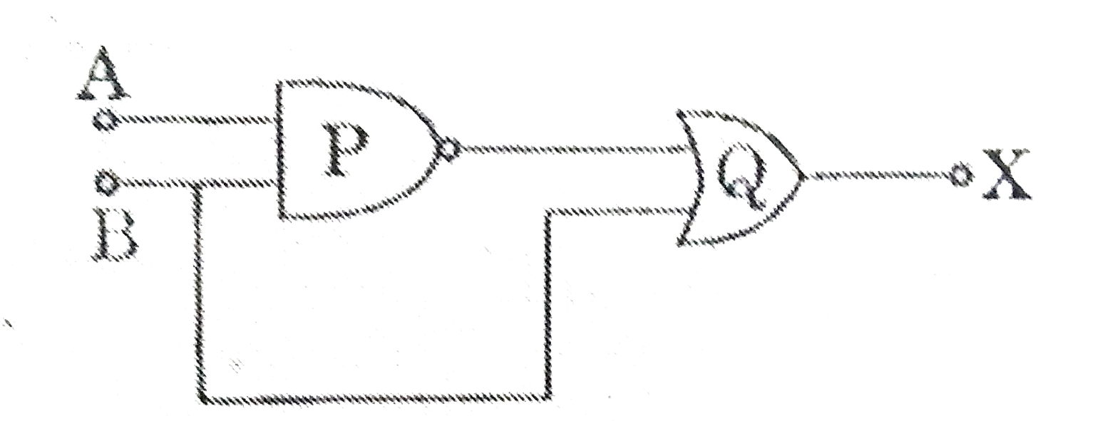
View Solution(i) Identify the logic gates marked P and Q in the given logic circuit.

(ii) Write down the output at X for the inputs A = 0 , B = 0 and A = 1 , B = 1.
View SolutionIdentify the logic gates marked P and Q in the circuit Fig. Write the truth table for this combination.

View Solution