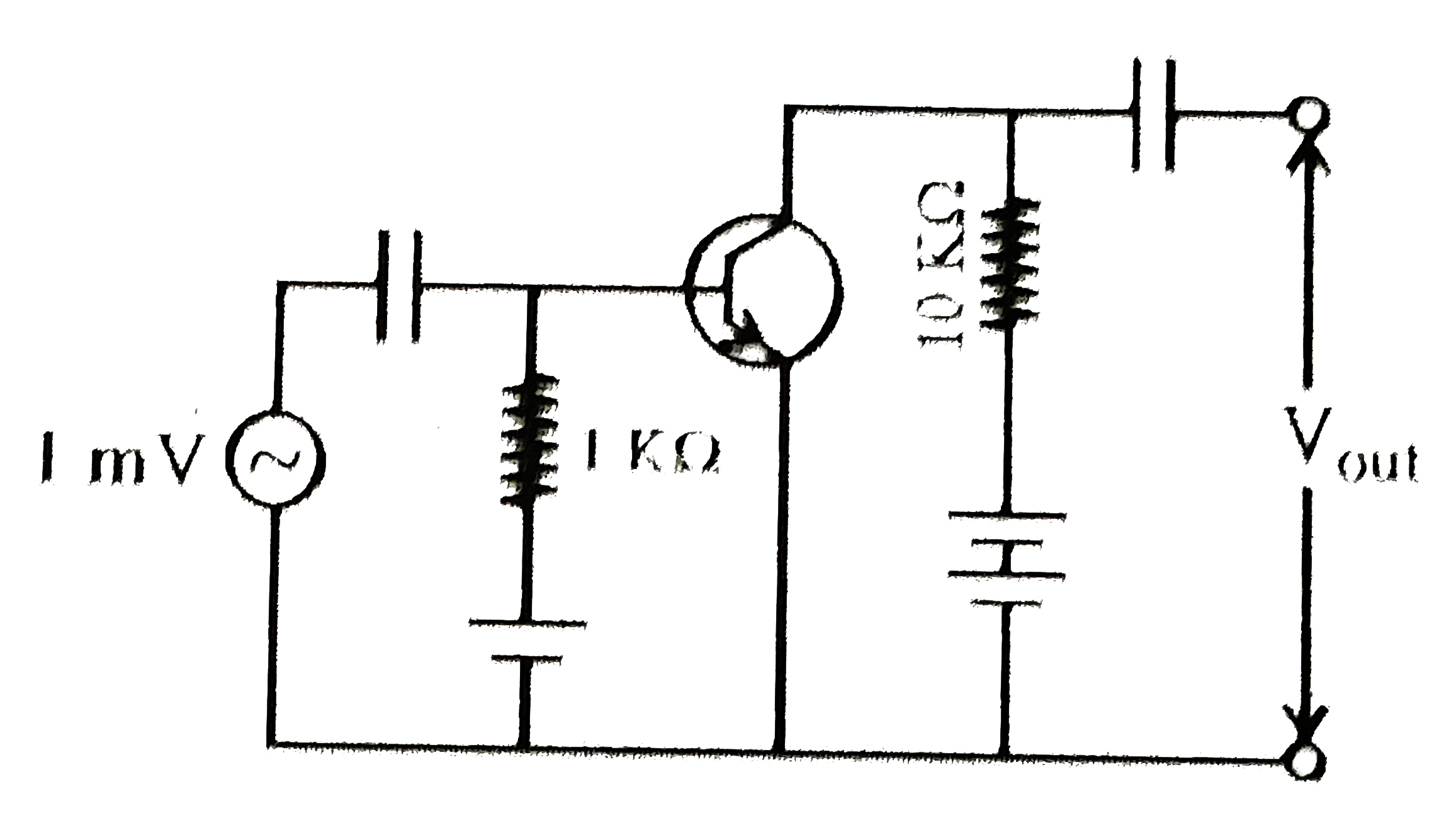
In a common-emitter amplifier circuit using an n-p-n transistor, the phase difference between the input and the output voltages will be Solution in Bengali
45∘
90∘
135∘
180∘
Step by step video & image solution for In a common-emitter amplifier circuit using an n-p-n transistor, the phase difference between the input and the output voltages will be by Physics experts to help you in doubts & scoring excellent marks in Class 12 exams.
Updated on:21/07/2023Topper's Solved these Questions
- QUESTION PAPER OF NEET 2017BOOK - CHHAYA PUBLICATIONCHAPTER - QUESTION PAPER OF NEET 2017EXERCISE - QUESTION PAPERS OF (NEET) (2017)
39 Videos
- QUESTION PAPER OF NEET 2017BOOK - CHHAYA PUBLICATIONCHAPTER - QUESTION PAPER OF NEET 2017EXERCISE - PART -B (SECTION-II )
2 Videos
- QUANTUM THEORYBOOK - CHHAYA PUBLICATIONCHAPTER - QUANTUM THEORYEXERCISE - CBSE Scanner
29 Videos
- QUESTION PAPER OF NEET 2018BOOK - CHHAYA PUBLICATIONCHAPTER - QUESTION PAPER OF NEET 2018EXERCISE - QUESTIONS
58 Videos
Similar Questions
A molecule of a substance has permanent dipole moment p. A mole of this substance is polarised by applying a strong electrostatic field E. The direction of the field is suddenly changed by an angle of 60∘. If N is the Avogadro's number the amount of work done by the field is
View SolutionWhat will be the change in focal length f of a concave mirror when immersed in a liquid of refractive index n?
View SolutionDefine the terms (i) 'cut-off voltage' and (ii) 'threshold frequency' in relation to phenomenon of photoelecric effect.
Using Einstein's photoelectric equation show how the cutt-off voltage and threshold frequency for a given photosensitive material can be determined with the help of a suitable plot/graph.
View SolutionIt is found that if a neutron suffers an elastic collinear collision with deuterium at rest, fractional loss of its energy is pd, while for its similar collision with carbon nucleus at rest, fractional loss of energy is pc. The values of pd and pc are respectively
View SolutionIn common emitter transistor amplifier circuit, the input signal voltage and the output collector voltage are ..............phase.
View SolutionDraw a labelled circuit diagram for a common emitter amplifier using n-p-n transistor. Write down the expression for its voltage gain. What is the phase difference between input and output signals?
View SolutionWith the help of a labelled circuit diagram, explain how an n-p-n transistor can be used as an amplifier in common-emitter configuration. Explain how the input and output voltages are out of phase by 1800 for a common-emitter transistor amplifier.
View SolutionDraw the circuit diagram of a common emitter amplifier using n-p-n transistor. What is the phase difference between the input signal and output voltage? State two reasons why a common emitter amplifier is preferred to a common base amplifier.
View SolutionIn the following common emitter configuration, and n-p-n transistor with current gain beta=100 is used. The output voltage of the amplifier will be
View SolutionIn a common emitter amplifier circuit using an n-p-n transistor, the phase difference between the input and the output voltages will be:-
View Solutionn - p - n ट्रांजिस्टर से बनाये हुए एक उभयनिष्ठ-उत्सर्जक प्रवर्धक परिपथ में निवेशित तथा निर्गत विभवों के बीच कलान्तर का मान होगा :
View SolutionIn the following common emitter configuration an n-p-n transistor with current gain β = 100 is used. The output voltage of the amplifier will be

View SolutionDraw a circuit diagram of a CE amplifier by using n-p-n transistor and show input and output voltages graphically.
View SolutionIn a common-emitter amplifier circuit using an n-p-n transistor the phase differene between the input and the output voltages will be
View Solutionट्रान्जिस्टर के उभयनिष्ठ उत्सर्जक प्रवर्धक परिपथ के लिए निवेशी एवं निर्गत सिग्नल के मध्य कलान्तर होता है :
View SolutionIn the following common emitter configuration an n-p-n transistor with current gain alpha = 100 is used . The output voltage of the amplifier will be :
View Solution
